Hardware layout and configuration UM1956
20/37 UM1956 Rev 5
6.9 USART virtual communication
Thanks to SB2 and SB3, the USART interface of STM32 available on PA2 (TX) and PA15
(RX), can be connected to ST-LINK/V2-1. When USART is not used it is possible to use PA2
as Arduino Nano A7. Refer to Table 7.
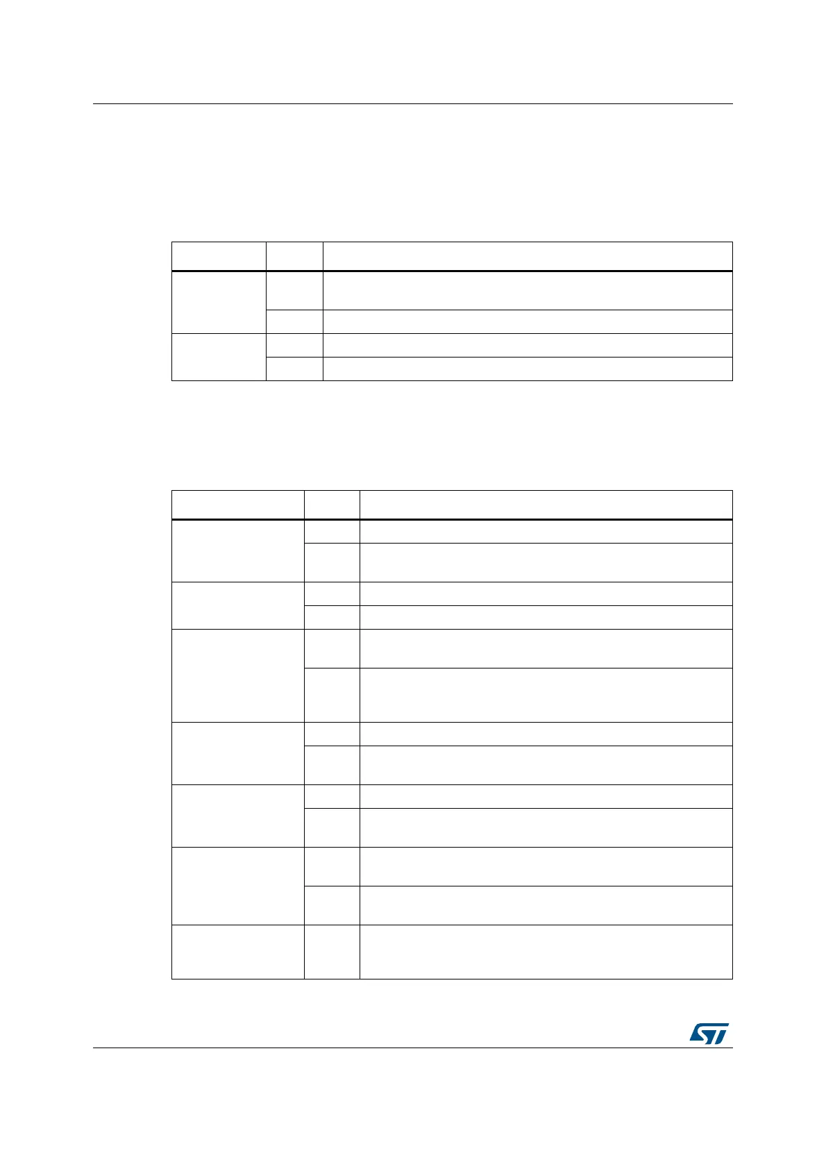
Table 7. Virtual communication configuration
Bridge State
(1)
1. The default configuration is reported in bold style.
SB2
OFF
PA2 is connected to CN4 pin 5 as Arduino Nano analog input A7 and
disco
nnected from ST-LINK USART.
ON PA2 is connected to ST-LINK as virtual Com TX (default).
SB3
OFF PA15 is not connected.
ON PA15 is connected to ST-LINK as virtual Com RX (default).
6.10 Solder bridges
Description
Table 8. Solder bridges
Bridge State
(1)
Description
SB10 (VREF+)
ON VREF+ on STM32 is connected to VDD.
OFF
VREF+ on STM32 is not connected to VDD and it is provided by
p
in 13 of CN4.
SB15 (LD3-LED)
ON Green user LED LD3 is connected to
D13 of Arduino Nano signal.
OFF Green user LED LD3 is not connected.
SB9 (NRST)
ON
The NRST signal of ST-LINK is conn
ected to the NRST pin of the
STM32.
OFF
The NRST signal of ST-LINK is not conn
ected to the NRST pin of
the STM32, when used external power (+3V3, +5 V) as power
supply.
SB11 (PB2/VSS)
ON Pin 16 of STM32 (U2) is connected to
VSS.
OFF
Pin 16 of STM32 (U2) is not connected to
VSS, and used as GPIO
PB2 for STM32F031.
SB13 (PB8/VSS)
ON Pin 32 of STM32 (U2) is connected to
VSS.
OFF
Pin 32 of STM32 (U2) is not connected to
VSS, and used as GPIO
PB8 for STM32F031.
SB12 (PB8/BOOT0)
ON
Pin 31 of STM32 (U2) is connected to GND via 10K pull-down and
used
as BOOT0.
OFF
Pin 16 of STM32 (U2) is not connected and is GPIO PB8 for
STM32
F042.
SB16 ON
STM32 PB6 is connected to CN4 pin 7 for I
2
C SDA support on
Arduino Nano A5. In such case STM32 PB6 does not support
Arduino Nano D5 and PA6 must be configured as input floating.

 Loading...

