6.2 Default board configuration
Table 4. Default jumper settings
Jumper Definition Default position Comment
CN2 SWD interface
[1-2]
[3-4]
On-board ST-LINK/V2-1 debugger
JP5 5 V power selection [1-2] 5 V from ST-LINK
JP1 STLK reset OFF No STLK reset
JP6 IDD measurement ON STM32 VDD current measurement
6.3 Cuttable PCB
The STM32 Nucleo-64 board is divided into two parts: the ST-LINK part and the target MCU part. The ST-LINK
PCB part is cuttable to reduce the board size. In this case, the remaining target MCU part is only powered by VIN,
E5V, and 3.3V on CN7 morpho connectors, or VIN and 3.3V on CN6 ARDUINO
®
connector. And it is still possible
to use the ST-LINK part to program the main MCU using wires between CN7 and SWD signals available on the
ST morpho connectors.
6.4 Embedded ST-LINK/V2-1
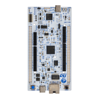
The ST-LINK/V2-1 programming and debugging tool is integrated into the NUCLEO-C031C6 Nucleo-64 board.
The additional features supported on the ST-LINK/V2-1 are:
• USB software re-enumeration
• Virtual COM port interface on USB
• Mass storage interface on USB
• Registers read/write interface on USB (Not available on Nucleo)
• USB power management request for more than 100 mA power on USB
The following features are no more supported on the ST-LINK/V2-1:
• SWIM interface
• Minimum application voltage supported by Nucleo limited to 3 V
• Standalone version does not exist. Only Nucleo and future discovery support V2-1.
For information about debugging and programming features, refer to the user manual ST-LINK/V2 in-circuit
debugger/programmer for STM8 and STM32 (UM1075), which describes in detail all the ST-LINK/V2 and ST-
LINK/V2-1 common features.
The embedded ST-LINK/V2-1 is usable in two different ways according to the jumper states (Refer to Table 5):
• Program/debug the on‑board STM32,
• Or program/debug an STM32 in an external application board using a cable connected to the SWD
connector.
Table 5. ST-LINK jumper configuration
Jumper
Definition Default position Comment
CN2 T_SWCLK / T_SWDIO
[1-2]
[3-4]
ST-LINK/V2-1 functions enabled for on-board
programming (Default setting)
OFF
OFF
ST-LINK/V2-1 functions enabled from external
connector (SWD supported)
6.4.1 Drivers
ST-LINK/V2-1 requires a dedicated USB driver, which, for Windows 7
®
, Windows 8
®
and Windows 10
®
, is
available from www.st.com.
UM2953
Default board configuration
UM2953 - Rev 1
page 11/32