6.5 Power supply and power selection
6.5.1 External power supply input
The STM32 Nucleo-64 board is designed to be powered by several DC power supplies. It is possible to supply the
STM32 Nucleo-64 board with any of the following sources:
• 5V_USB_STLK from the ST-LINK USB connector
• VIN (7 to 12 V) from the ARDUINO
®
or ST morpho connector
• E5V from the ST morpho connector
• 5V_USB_CHG from the ST-LINK USB connector
• 3.3 V from the ARDUINO
®
or ST morpho connector
Note: If an external 5 V DC power source is used, the Nucleo board must be powered by a power supply unit or by
a piece of auxiliary equipment complying with the EN-60950-1: 2006+A11/2009 standard and must be safety
extra
‑
low voltage (SELV) with limited power capability.
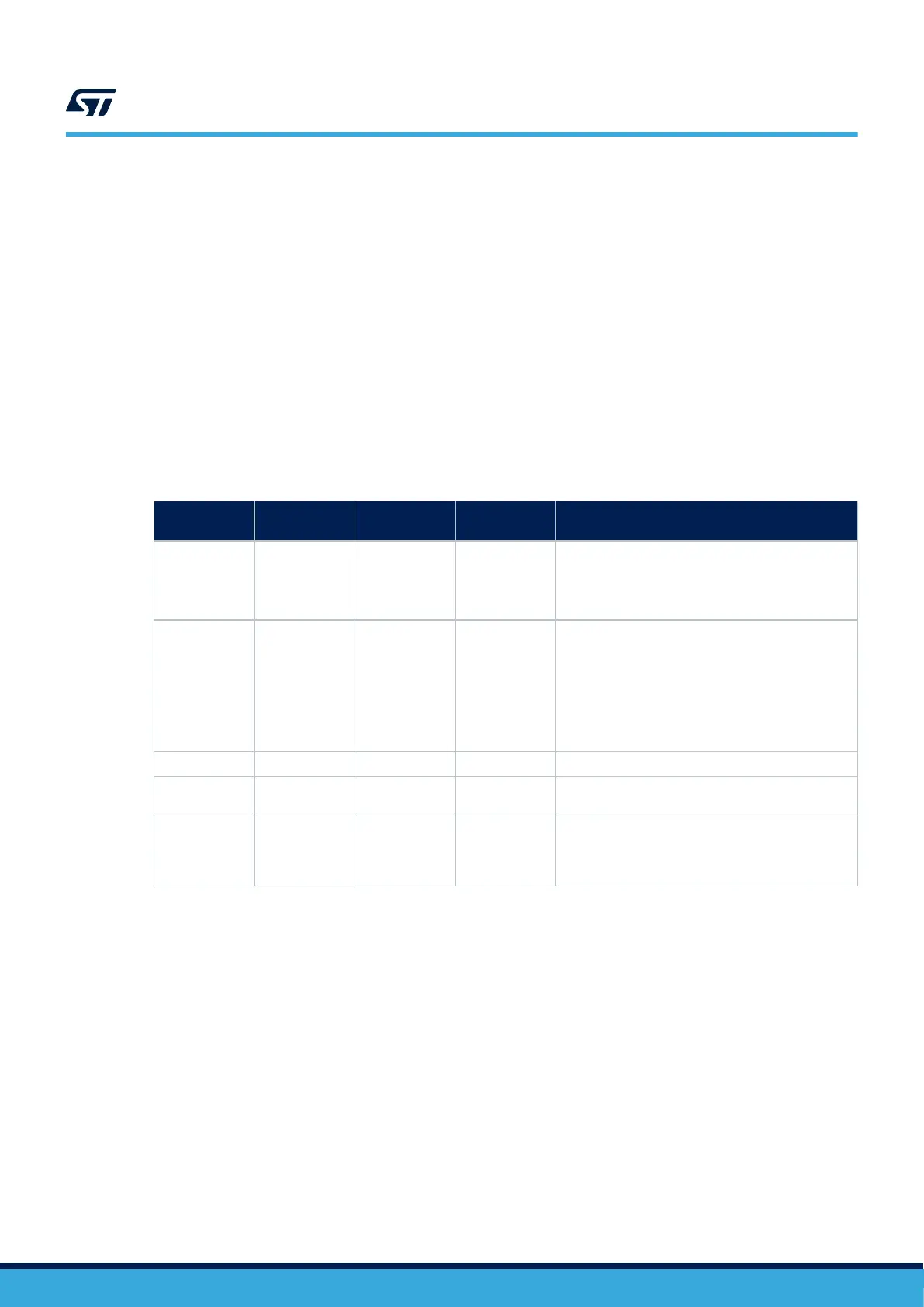
The power supply capabilities are shown in Table 7.
Table 7. Power supply capabilities
Input power
Connector
pins
Voltage range
Maximum
current
Limitation
5V_USB_STLK CN1 pin 1 4.75 to 5.25 V 500 mA
The maximum current depends on the USB
enumeration:
• 100 mA without enumeration
• 500 mA with good enumeration
VIN
CN6 pin 8
CN7 pin 24
7 to 12 V 800 mA
From 7 to 12 V only and the input current capability
is linked to the input voltage:
• 800 mA input current when VIN = 7 V
• 450 mA input current when 7 V < VIN < 9 V
• 300 mA input current when 9 V < VIN < 10V
• Less than 300 mA input current when
10 V < VIN
E5V CN7 pin 6 4.75 to 5.25 V 500 mA -
5V_USB_CHG CN1 pin 1 4.75 to 5.25 V 500 mA
Maximum current depends on the USB wall charger
used to power the Nucleo board.
3V3
CN6 pin 4
CN7 pin 16
JP6 pin 1
3.0 to 3.6 V -
Used when the PCB ST-LINK part is not used or
remove SB2 and SB23
5V_ST_LINK is a DC power with limitations from the ST-LINK USB connector (USB type Micro-B connector of
ST-LINK/V2-1). In this case, the JP5 jumper must be on pins 1 and 2 to select the STLK power source on the JP5
silkscreen. This is the default setting. If the USB enumeration succeeds, the STLK power is enabled, by asserting
the PWR_ENn signal coming from the STM32F103CBT6 ST-LINK microcontroller. This pin is connected to an
STMPS2141STR power switch, which powers the board. This power switch also features a current limitation to
protect the PC in case of a short-circuit on board, detected with current higher than 750 mA.
The STM32 Nucleo-64 board and its shield are powerable from the CN1 ST-LINK USB connector, but only the
ST-LINK circuit is powered before USB enumeration because the host PC only provides 100 mA to the board
at that time. During the USB enumeration, the STM32 Nucleo-64 board requires 500 mA of current from the
host PC. If the host can provide the required power, the enumeration ends by a SetConfiguration command
and then, the STMPS2141STR power transistor is switched ON, the LD3 green LED is turned ON, thus the
STM32 Nucleo-64 board and its shield request no more than 500 mA current. If the host is not able to provide
the required current, the enumeration fails. Therefore the power switch transistor stays OFF and the MCU part
including the extension board is not powered. As a consequence, the LD3 green LED stays turned OFF. In this
case, it is mandatory to use an external power supply.
USB power: STLK configuration: Jumper JP5 [1-2] (STLK silkscreen) must be connected as shown in Figure 3
and Table 9.
UM2953
Power supply and power selection
UM2953 - Rev 1
page 13/32