6.9 VCP communication
The two UART interfaces of the STM32 are used for VCP communication:
1. UART2 from PA2/PA3
2. UART1 from PB6/PB7
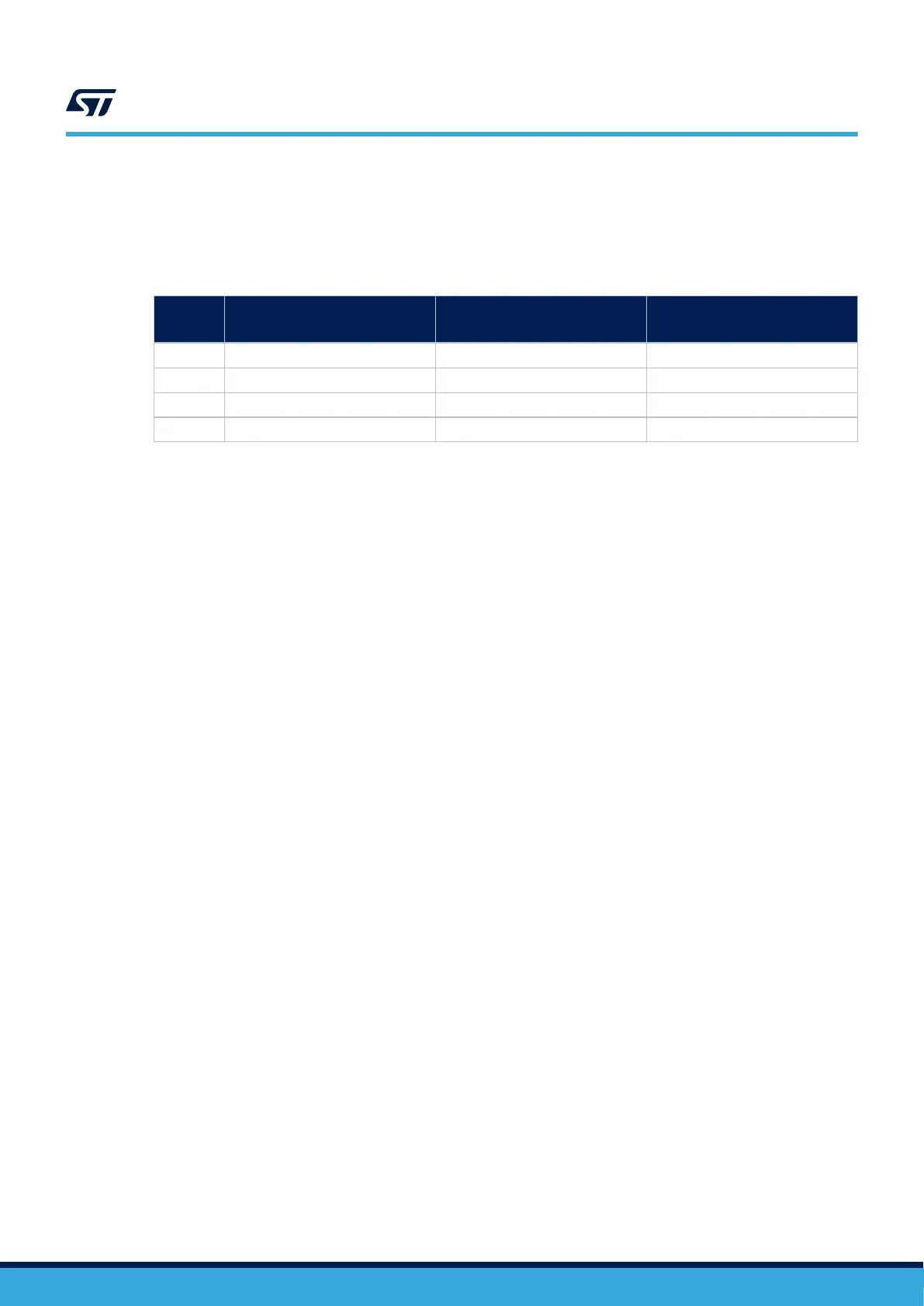
Table 8. VCP communication
Pin name Function
Virtual COM port
(Default configuration
ST morpho connection
PA2 USART2 TX SB27 ON SB27 OFF
PA3 USART2 RX SB32 ON SB32 OFF
PB6 USART1 TX SB31 ON SB31 OFF
PB7 USART1 RX SB33 ON SB33 OFF
6.10 LEDs
Four LEDs are available on the STM32 Nucleo-64 board. The four LEDs are located on the top side of the board:
1. LD1 COM: LD1 is a bi-colored LED. the LD1 default status is red. LD1 turns to green to indicate that
communication is in progress between the PC and the ST-LINK/V2-1 as follow:
– Slow blinking red and OFF: At power-on before USB initialization
– Fast blinking red and OFF: After the first correct communication between the PC and the ST-LINK/V2-1
(enumeration)
– Red LED ON: When initialization between the PC and the ST-LINK/V2-1 successfully ends
– Green LED ON: After successful STM32 communication initialization
– Blinking red and green: During communication with STM32
– Green ON: Communication successfully ends.
– Orange ON: Communication ends with failure.
2. LD2 5V_USB_CHG: This red LED is ON when overcurrent is detected on USB V
BUS
. The LED gives the
information that more than 500 mA is requested on V
BUS
. In this case, it is recommended to supply the
board with E5V, VIN, or in USB_CHARGER mode.
3. LD3 5V_PWR: This green LED is ON when the STM32 Nucleo-64 board is powered by a 5 V source.
4.
LD4 USER: This green LED is a user LED connected to D13 ARDUINO
®
signal corresponding to PA5
STM32 I/O. To light the LED a HIGH logic state must be written in the corresponding GPIO. A transistor is
used to drive the LED when the I/O voltage is 1.8 V. LD4 consumption does not impact the VDD STM32
power measurement, since LD4 is isolated from it.
6.11 Push‑buttons
Two push‑buttons:
1. B1 USER: User and wake-up button connected to the PC13 I/O pin 3 of the STM32 microcontroller
2. B2 RESET: Push‑button connected to NRST is used to reset the STM32 microcontroller.
The blue and black plastic hats placed on these push‑buttons are removable if necessary when a shield or an
application board is plugged on top of the Nucleo board. This avoids pressure on the buttons and consequently a
possible permanent target MCU reset.
6.12 I
DD
measurement
The JP6 IDD‑labeled jumper allows the consumption of the STM32 microcontroller measurement by removing the
jumper and connecting an ammeter:
• Jumper ON: STM32 Microcontroller is powered (Default configuration)
• Jumper OFF: An ammeter must be connected to measure the STM32 microcontroller current. If there is no
ammeter, the STM32 microcontroller is not powered.
UM2953
VCP communication
UM2953 - Rev 1
page 16/32