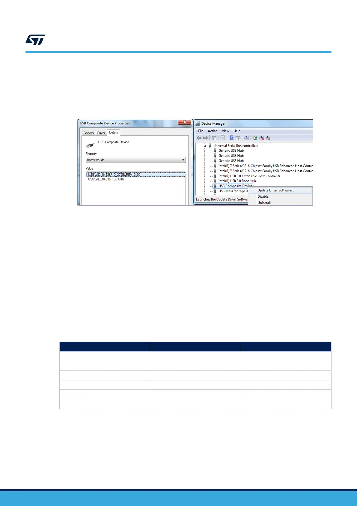
In cases where the STM32 Nucleo-64 board is connected to the PC before the driver is installed, some STM32
Nucleo-64 interfaces might be declared as “Unknown” in the PC device manager. In this case, the user must
install the dedicated driver files and update the driver of the connected device from the device manager, as shown
in Figure 6.
Note: It is preferable to use the USB Composite Device handle for a full recovery.
Figure 6. USB composite device
6.4.2 ST-LINK/V2-1 firmware upgrade
ST-LINK/V2-1 embeds a firmware mechanism for the in-situ upgrade through the USB port. As the firmware may
evolve during the lifetime of the ST-LINK/V2-1 product (for example new functionalities, bug fixes, support for
new microcontroller families), visiting the www.st.com website is recommended before starting to use the STM32
Nucleo-64 board, then periodically to stay up-to-date with the latest firmware version.
6.4.3 Using ST-LINK/V2-1 to program/debug the on-board STM32
To program the on‑board STM32, plug in the two jumpers on CN2, as shown in Figure 3 but do not use the CN3
connector as that may disturb communication with the on‑board STM32 microcontroller.
6.4.4 Using ST-LINK/V2-1 to program/debug an external STM32 application
It is easy to use ST-LINK/V2-1 to program the STM32 on an external application. Remove the two jumpers from
CN2 as shown in Figure 3, and connect the application to the CN3 debug connector according to Table 6.
Note: SB23 must be OFF if CN3 pin 5 is used in the external application.
Table 6. CN3 SWD debug connector
Pin number Signal name Designation
1 VDD_TARGET VDD from the application
2 SWCLK SWD clock
3 GND Ground
4 SWDIO SWD data I/O
5 NRST Target MCU reset
6 SWO Reserved
UM2953
Embedded ST-LINK/V2-1
UM2953 - Rev 1
page 12/32