Reference design AN3320
24/29 Doc ID 18267 Rev 2
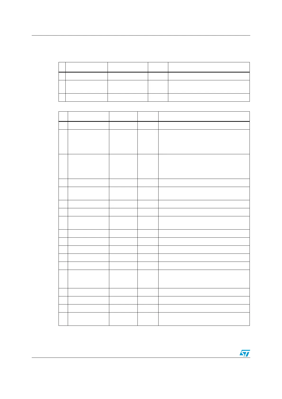
6.2 Component references
Table 4. Mandatory components
Id Components name Reference Quantity Comments
1 Microcontroller STM32F207IG(H6) 1 176-pin package
2 Capacitors 100 nF 16
Ceramic capacitors (decoupling
capacitors)
3 Capacitor 10 µF 1 Ceramic capacitor (decoupling capacitor)
Table 5. Optional components
Id Components name Reference Quantity Comments
1Resistor 10 kΩ 5 pull-up and pull-down for JTAG and Boot mode.
2Resistor 390 Ω 1
Used for HSE: the value depends on the
crystal characteristics.
This resistor value is given only as a typical
example.
3Resistor 0 Ω 1
Used for LSE: the value depends on the crystal
characteristics.
This resistor value is given only as a typical
example.
4 Capacitor 100 nF 2 Ceramic capacitor.
5 Capacitor 2 pF 2
Used for LSE: the value depends on the crystal
characteristics.
6 Capacitor 1 µF 2 Used for V
DDA
and V
REF
.
7 Capacitor 2.2 µF 2 Used for internal regulator when it is on.
8 Capacitor 20 pF 2
Used for HSE: the value depends on the
crystal characteristics.
9 Quartz 25 MHz 1 Used for HSE.
10 Quartz 32 kHz 1 Used for LSE.
11 JTAG connector HE10 1
12 Transil diode 5 V-400 W 11 For JTAG protection.
13 Resistor 22 Ohm 11 For JTAG protection.
14 Battery 3V3 1
If no external battery is used in the application,
it is recommended to connect V
BAT
externally
to V
DD.
15 Switch 3V3 2 Used to select the right boot mode.
16 Push-button B1 1
17 Jumper 3 pins 2 Used to select V
BAT
source, and REGOFF pin.
18
Debug trace
connector
FTSH-110-
01-L-DV
1 Used for JTAG/SWD and debug trace.
 Loading...


