Recommendations AN3320
22/29 Doc ID 18267 Rev 2
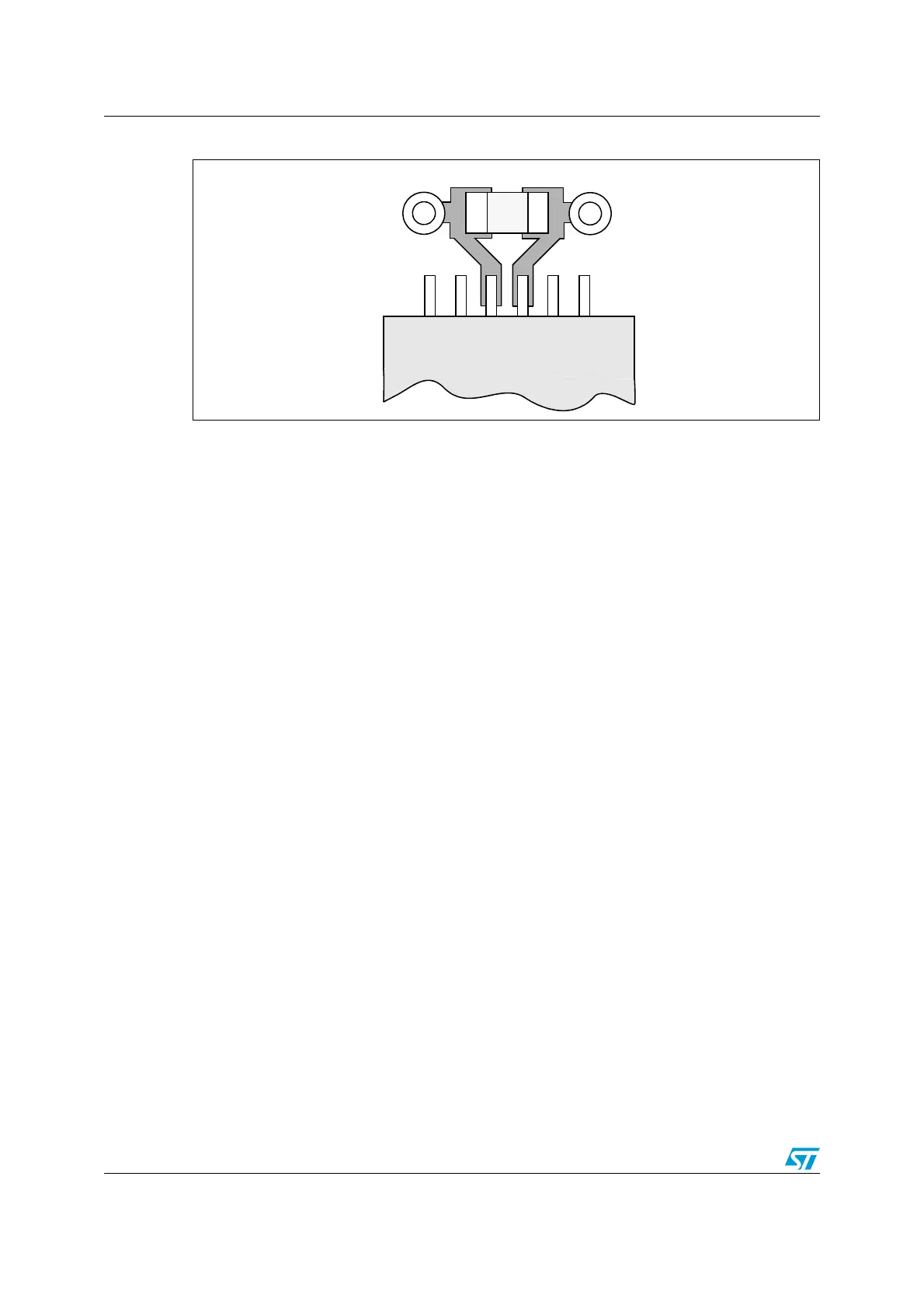
Figure 13. Typical layout for V
DD
/V
SS
pair
5.5 Other signals
When designing an application, the EMC performance can be improved by closely studying:
● Signals for which a temporary disturbance affects the running process permanently
(the case of interrupts and handshaking strobe signals, and not the case for LED
commands).
For these signals, a surrounding ground trace, shorter lengths and the absence of
noisy and sensitive traces nearby (crosstalk effect) improve EMC performance.
For digital signals, the best possible electrical margin must be reached for the two
logical states and slow Schmitt triggers are recommended to eliminate parasitic states.
● Noisy signals (clock, etc.)
● Sensitive signals (high impedance, etc.)
5.6 Unused I/Os and features
All microcontrollers are designed for a variety of applications and often a particular
application does not use 100% of the MCU resources.
To increase EMC performance, unused clocks, counters or I/Os, should not be left free, e.g.
I/Os should be set to “0” or “1”(pull-up or pull-down to the unused I/O pins.) and unused
features should be “frozen” or disabled.
Via to V
SS
Via to V
DD
Cap.
V
DD
V
SS
STM32F20xxx/21xxx
 Loading...


