Clocks AN3320
12/29 Doc ID 18267 Rev 2
2 Clocks
Three different clock sources can be used to drive the system clock (SYSCLK):
● HSI oscillator clock (high-speed internal clock signal)
● HSE oscillator clock (high-speed external clock signal)
● PLL clock
The devices have two secondary clock sources:
● 32 kHz low-speed internal RC (LSI RC) that drives the independent watchdog and,
optionally, the RTC used for Auto-wakeup from the Stop/Standby modes.
● 32.768 kHz low-speed external crystal (LSE crystal) that optionally drives the real-time
clock (RTCCLK)
Each clock source can be switched on or off independently when it is not used, to optimize
the power consumption.
Refer to the STM32F20xxx/21xxx reference manual RM0033 for the description of the clock
tree.
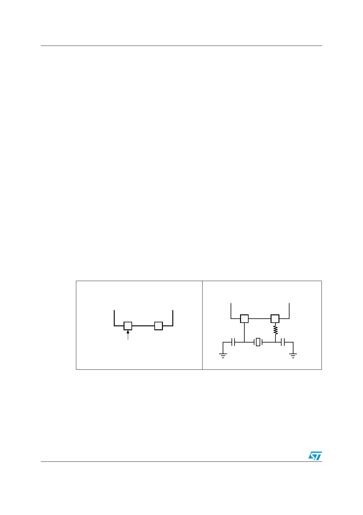
2.1 HSE OSC clock
The high-speed external clock signal (HSE) can be generated from two possible clock
sources:
● HSE external crystal/ceramic resonator (see Figure 7)
● HSE user external clock (see Figure 6)
1. The value of R
EXT
depends on the crystal characteristics. Typical value is in the range of 5 to 6 R
S
(resonator series resistance).
2. Load capacitance C
L
has the following formula: C
L
= C
L1
x C
L2
/ (C
L1
+ C
L2
) + C
stray
where: C
stray
is the pin
capacitance and board or trace PCB-related capacitance. Typically, it is between 2 pF and 7 pF. Please
refer to Section 5: Recommendations on page 21 to minimize its value.
Figure 6. HSE external clock Figure 7. HSE crystal/ceramic
resonators
OSC_OUTOSC_IN
External source
(Hi-Z)
ai14369
Hardware configuration
/3#?/54/3#?).
AIA
34-&
2
%84
#
,
#
,
(ARDWARECONFIGURATION
 Loading...


