Power supplies AN3320
10/29 Doc ID 18267 Rev 2
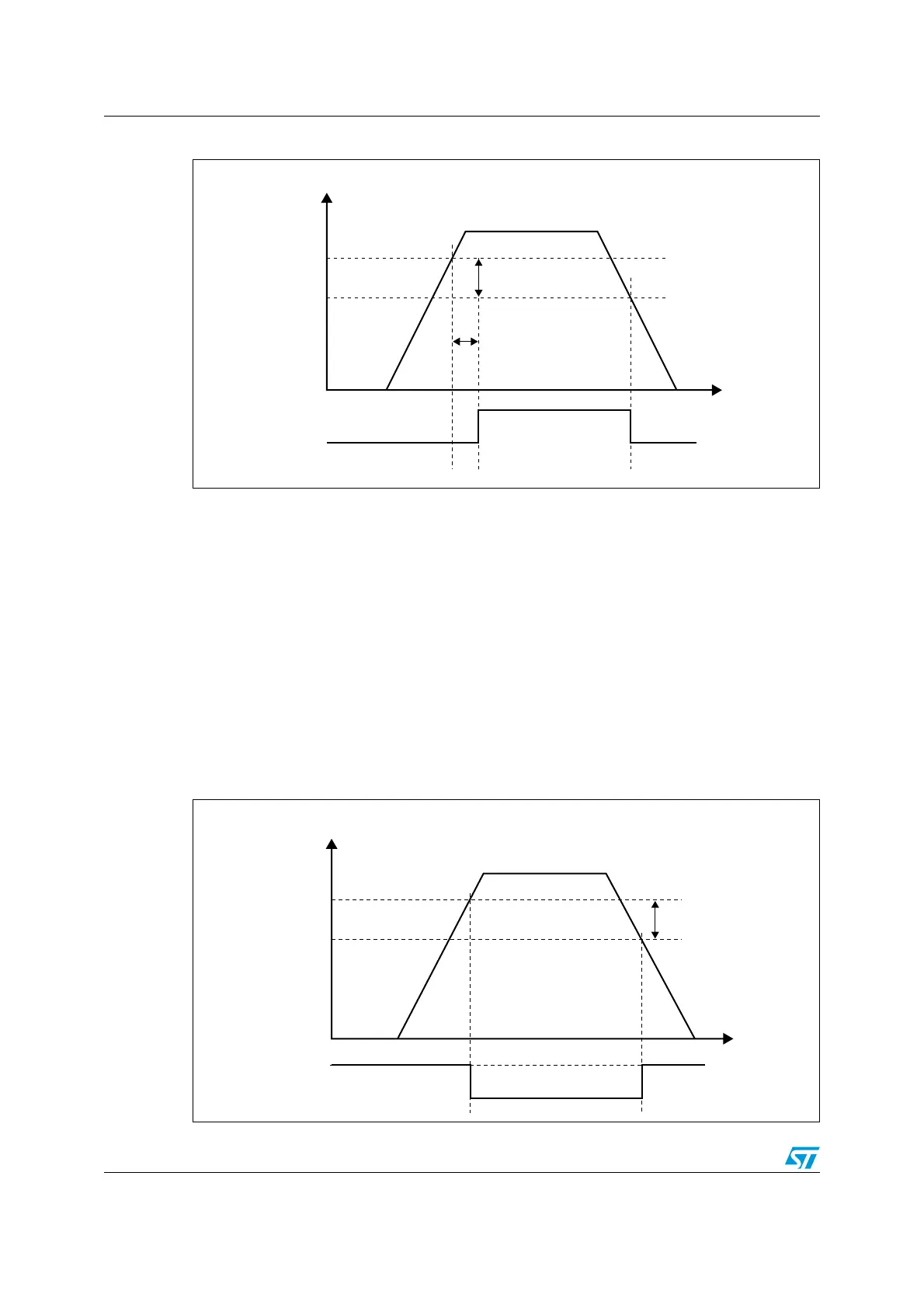
Figure 3. Power-on reset/power-down reset waveform
1. t
RSTTEMPO
is approximately 2.6 ms. V
POR/PDR
rising edge is 1.74 V (typ.) and V
POR/PDR
falling edge is
1.70 V (typ.). Refer to STM32F20xxx/21xxx datasheets for actual value.
1.3.2 Programmable voltage detector (PVD)
You can use the PVD to monitor the V
DD
power supply by comparing it to a threshold
selected by the PLS[2:0] bits in the Power control register (PWR_CR).
The PVD is enabled by setting the PVDE bit.
A PVDO flag is available, in the Power control/status register (PWR_CSR), to indicate
whether V
DD
is higher or lower than the PVD threshold. This event is internally connected to
EXTI Line16 and can generate an interrupt if enabled through the EXTI registers. The PVD
output interrupt can be generated when V
DD
drops below the PVD threshold and/or when
V
DD
rises above the PVD threshold depending on the EXTI Line16 rising/falling edge
configuration. As an example the service routine can perform emergency shutdown tasks.
Figure 4. PVD thresholds
6
$$
0/2
0$2
M6
HYSTERESIS
4EMPORIZATION
T
2344%-0/
2%3%4
AIB
6
0/20$2
FALLINGEDGE
6
0/20$2
RISINGEDGE
6
$$
M6
HYSTERESIS
06$THRESHOLD
06$OUTPUT
AIB
6
06$
FALLINGEDGE
6
06$
RISINGEDGE
 Loading...


