EasyManua.ls Logo

ST STM32H745I-DISCO

ST STM32H745I-DISCO
55 pages
To Next Page IconTo Next Page
Loading...
Introduction
The STM32H745I-DISCO and STM32H750B-DK Discovery kits are complete demonstration and development platforms for
STMicroelectronics Arm
®
Cortex
®
-M7 and -M4 dual-core-based STM32H745XI (STM32H745XIH6 order code) and
STM32H750XB (STM32H750XBH6 order code) microcontrollers. Both devices feature four I
2
Cs, six SPIs with three multiplexed
simplex I
2
Ss, two SD/SDIO/DMMC interfaces, four USARTs, four UARTs, one LPUART, two CAN controllers, three 16-bit ADCs,
two 12-bit DACs, four SAIs, 8- to 14-bit digital camera interface, 1 Mbyte (STM32H745XIH6) or 128 Kbytes (STM32H750XBH6)
of internal SRAM and 2 Mbytes of Flash memory, a USB OTG HS and a USB OTG FS, an Ethernet MAC interface, an FMC
interface, a Quad-SPI interface, and SWD debugging support. The STM32H745I-DISCO and STM32H750B-DK Discovery kits
enable users to quickly get started and develop applications.
In addition, the STM32H745I-DISCO and STM32H750B-DK, shown in Figure 1 and Figure 2, can be used as a reference
design for user application prototyping before porting to the final product.
The full range of hardware features available on the board helps users improve application development by an evaluation of
almost all peripherals (such as USB OTG FS, Ethernet 10/100Mb/s, eMMC, USART, SAI Audio DAC stereo with audio jack
input and output, MEMS digital microphone, SDRAM, Quad-SPI Flash memory, and RGB LCD interface with capacitive multi-
touch panel). ARDUINO
®
Uno V3 connectors provide easy connection to extension shields or daughterboards for specific
applications.
STLINK-V3E is integrated into the board, as an embedded in-circuit debugger and programmer for the STM32 microcontroller
and the USB Virtual COM port bridge.
The STM32H745I-DISCO and STM32H750B-DK boards come with the STM32CubeH7 MCU package, which provides an
STM32 comprehensive software HAL library as well as various software examples.
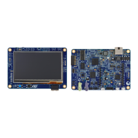
Figure 1.
STM32H745I-DISCO and STM32H750B-DK
boards (top view)
Figure 2. STM32H745I-DISCO and STM32H750B-DK
boards (bottom view)
Pictures are not contractual. PCB colors may differ.
Discovery kits with STM32H745XI and STM32H750XB microcontrollers
UM2488
User manual
UM2488 - Rev 4 - September 2019
For further information contact your local STMicroelectronics sales office.
www.st.com

Table of Contents

Question and Answer IconNeed help?

Do you have a question about the ST STM32H745I-DISCO and is the answer not in the manual?

ST STM32H745I-DISCO Specifications

General IconGeneral
BrandST
ModelSTM32H745I-DISCO
CategoryMicrocontrollers
LanguageEnglish

Summary

Introduction

Features

Ordering Information

Product Marking

Marks on evaluation tools and specific device versions for identification.

Codification

Explanation of the meaning of the STM32H7XXY-DISCO/DK codification.

Development Environment

System Requirements

Defines the necessary operating systems and hardware for development.

Development Toolchains

Lists the supported software development tools and IDEs.

Demonstration Software

Details the preloaded demonstration software and its availability for download.

Conventions

Delivery Recommendations

Hardware Layout and Configuration

STM32 H745 I-DISCO and STM32 H750 B-DK Layout

Illustrates the top and bottom layouts of the discovery boards, identifying key components.

Embedded STLINK-V3 E

Describes the integrated STLINK-V3E debugger and programmer's capabilities.

Power Supply

Details the various 5V DC power supply options and necessary configurations.

Clock Sources

Lists the three available clock sources for the microcontrollers and STLK.

Reset Sources

Identifies the different sources that can trigger a reset on the discovery kits.

Buttons and LEDs

Summarizes the function and assignment of control ports to LED indicators.

Connectors

ARDUINO Uno V3 Connectors

Details the female connectors compatible with the ARDUINO standard for expansion.

CN13 USB OTGFS Micro-AB Connector

Provides pinout and description for the USB OTG_FS Micro-AB connector.

CN1 Ethernet RJ45 Connector

Details the pinout and associated LEDs for the Ethernet RJ45 connector.

LCD RGB Connector

Lists pin connections and descriptions for the LCD RGB interface.

CN2 STMod+ Connector

Describes the STMod+ connector for flexibility and expansion.

CN14 STLINK-V3 USB Micro-B Connector

Details the USB Micro-B connector used for STLINK-V3E connection.

CN16 TAG Connector

Provides pinout for the TAG connector used for programming and debugging.

CN4 STDC14 Connector

Details the STDC14 connector for programming/debugging via SWD.

CN15 USB Power Connector

Describes the USB Micro-B connector for board power supply.

STM32 H745 I-DISCO and STM32 H750 B-DK IO Assignment

Electrical Schematics

Related product manuals