Hardware and layout UM1574
30/48 Doc ID 023645 Rev 1
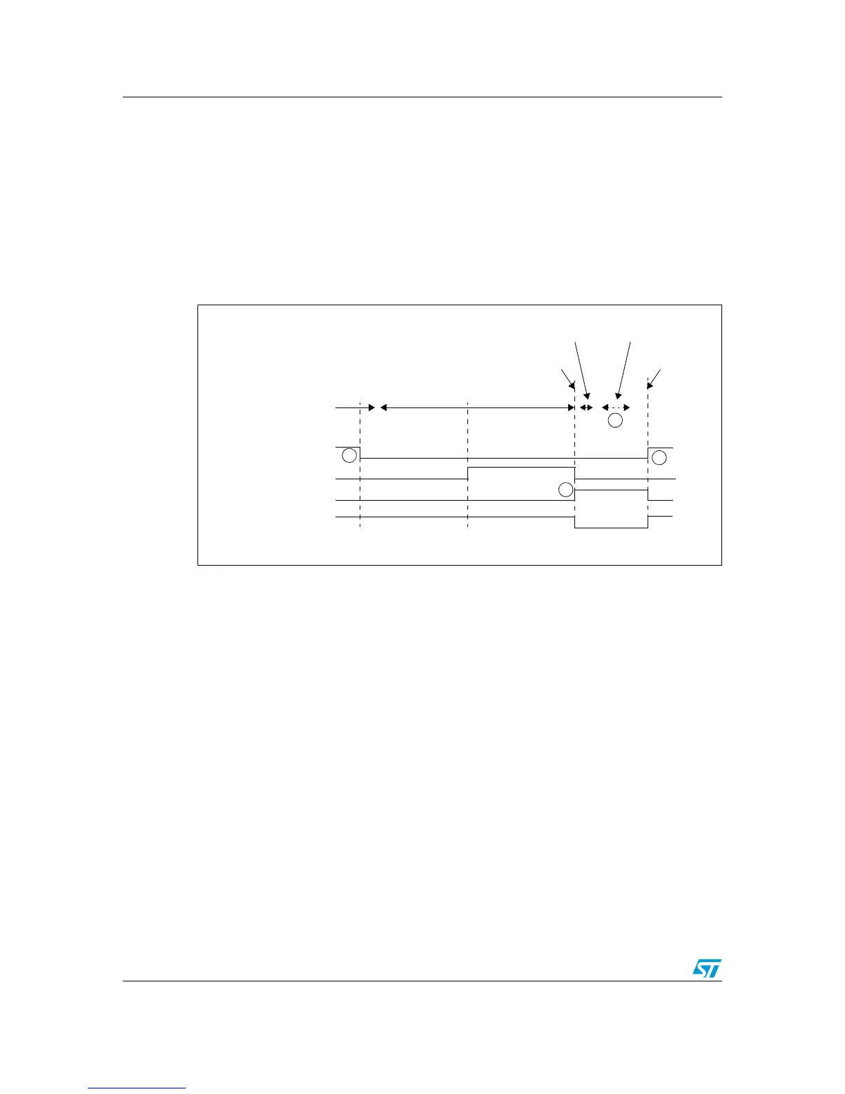
The measurement timing is given in Figure 17. In Low power modes, the 2 K resistor is
connected when the U5 switch goes off after entering Low power mode. The Q13 output of
the counter allows connection of the 2 K
resistor when the current I
DD
becomes very low.
Figure 17 shows how the counter and U5 ensure that, 150 ms after IDD_CNT_EN falling
edge, the shunt resistor R24 is connected between VDD_MCU and the power supply in
order to reduce the measurement range to 30 µA full scale (instead of 30 mA in Run mode).
Then after another 150 ms for current stabilization, R24 is shorted, the I
DD
measurement is
stored in C14, and the MCU is woken up. After wakeup, the MCU can measure the I
DD
current corresponding to the Low power mode stored in C14.
Figure 17. STM8AL board I
DD
Low power mode measurement timing diagram
● Ibias current measurement procedure
In Low power mode the bias current of operational amplifier input (U8 pin 4) is not negligible
compared to I
DD
current (typical Ibias is ~240 nA). To obtain a reliable STM8AL3L68T I
DD
measurement, it is mandatory to subtract the bias current from the I
DD
low power
measurement since MCU is not sinking the current. Ibias is measured during production test
and stored in the MCU EPROM. The demonstration software, Discover, uses this value to
display the correct I
DD
. The Ibias measurement procedure is part of the demonstration
software and can be launched if required.
The procedure for Ibias measurement (implemented in the package demo) is:
1. Power off the board (disconnect the USB cable).
2. Set jumper JP2 to OFF position (pins 1 and 2).
3. Push down USER2 button while powering on the board from the USB.
4. Wait at least 1 second before releasing USER2, the LCD displays the Ibias
measurement.
5. Power off the board (disconnect the USB cable).
6. Set jumper JP2 to ON position (pins 2 and 3). The Ibias value is now stored. The bias
current is then subtracted from the I
DD
measurement performed in Low power mode.