6
Connect a No. 8 AWG (8.4 sq. mm) solid copper bonding wire to the pressure
wire connector provided on the motor housing and to all metal parts of the
swimming pool, spa, or hot tub and to all electrical equipment, metal piping
or conduit within 5 feet (1.5 m) of the inside walls of swimming pool, spa, or
hot tub.
Wiring
Pump must be permanently connected to circuit. Table I gives correct wire
and circuit breaker sizes for the pump alone. If other lights or appliances are
also on the same circuit, be sure to add their amp loads to pump amp load
before figuring wire and circuit breaker sizes. (If unsure how to do this or if
this is confusing, consult a licensed electrician.) Use the load circuit breaker
as the master on-off switch.
Install a Ground Fault Circuit Interrupter (GFCI) in circuit; it will sense a short-
circuit to ground and disconnect power before it becomes dangerous to pool
users. For size of GFCI required and test procedures for GFCI, see manufac-
turer’s instruction.
In case of power outage, check GFCI for tripping (which will prevent normal
pump operation). Reset if necessary.
NOTICE: If you do not use conduit when wiring motor, be sure to seal wire
opening on end of motor to prevent dirt, bugs, etc., from entering.
Values given in table below are for PUMP ONLY. If additional acces-
sories are installed on pump motor circuit (heater, blower, etc.), in-
clude their amerage draw when figuring wire and circuit breaker sizes.
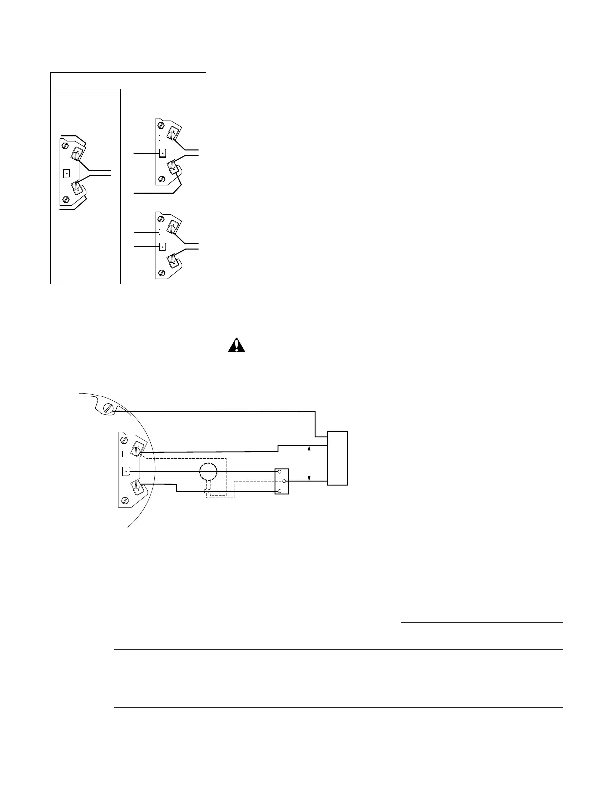
Optional Timer.
Rating given in "Recommended Fusing and Wiring Data" table.
Figure 3B – Remote switching for 115V 2-Speed pumps. Timer supply should be
unswitched.
TABLE I - RECOMMENDED FUSING AND WIRING DATA – 60 Cycle Motors
Serv. to Motor - Dist. in Ft. (M)
Pump Motor Branch Fuse Max Load Voltage/ 0-100' 101-200' 201-300'
Model HP Rating Amps* Amps Hz/Phase (0-30M) (30-60M) (60-90M)
LT1/6L 1/6 15 4.5 115/60/1 14(2) 14(2) 14(2)
LTACL 1/2 15 8.4 115/60/1 14(2) 12(3) 10(5.5)
LTADL 3/4 15 11.4 115/60/1 14(2) 10(5.5) 8(8.4)
LTAYDRL 3/4-1/8 15 10.0-3.0 115/60/1 14(2) 12(3) 10(5.5)
* Branch Short Circuit Protection (Non Time-Delay Fuse).