G
B
21
whenthetemperatureistoohigh.Themotorrestarts
automatically when normal temperature conditions
arerestored.
● To facilitate restart of the compressor, in addition
to the operations indicated, it is important to
return the button of the pressure switch to the
OFF position and then to ON again(fig. 2).
● Onsingle-phaseversions,presstheresetbuttonon
theterminalboxofthemotor(fig. 19).
● On 3-phase versions, operate manually on the
button of the pressure switch, returning this to the
ON position, or press the button of the thermal
cutoutinsidetheboxoftheelectricpanel(figures
2b & 20).
● Thesingle-phase versions are fitted with a pressure
switch equipped with a delayed closing air vent valve
(or with a valve located on the check valve) that
facilitates motor start-up; therefore a few-second
jet of air from this, with the reservoir empty, is to be
considerednormal.
● To guarantee machine safety, all the compressors
are fitted with a safety valve that is activated in the
caseoffailureofthepressureswitch.
● When fitting a tool, the flow of air in output must be
switchedoff.
● When using compressed air, you must know and
comply with the safety precautions to be adopted for
eachtypeofapplication(inflation,pneumatictools,
painting,washingwithwater-baseddetergentsonly,
etc.).
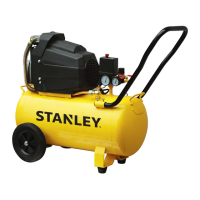
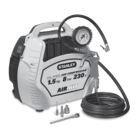
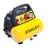
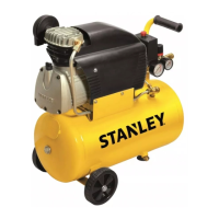
2. LAYOUT
1. Intakeairlter
2. Pressurevessel
3. Wheel
4. Guideroller(orsupportingfoot)
5. Quick-lockcoupling(regulatedcompressedair)
6. Pressuregauge(forreadingthepresettankpres-
sure)
7. Pressureregulator
8. ON/OFFswitch
9. Transportationhandle
10. Safetyvalve
11. Drainagescrewforcondensationwater
12. Pressuregauge(forreadingthetankpressure)
13. Quick-lockcoupling(unregulatedcompressedair)
14. Oilsealingplug(oillleropening)
15. Oildrainagescrew
16. Oillevelwindow
17. Bolt
18. Nut
19. Washer
20. Checkvalve
3. SCOPE OF USE
The compressor is designed for generating com-
pressedairfortoolsoperatedbycompressedair.
Please note that our equipment has not been designed
foruseincommercial,tradeorindustrialapplications.
Our warranty will be voided if the machine is used in
commercial, trade or industrial businesses or for equiv-
alentpurposes.
Themachineistobeusedonlyforitsprescribedpur-
pose.Anyotheruseisdeemedtobeacaseofmisuse.
Theuser/operatorandnotthemanufacturerwillbe
liable for any damage or injuries of any kind caused as
aresultofthis.
4. POINTS TO NOTE WHEN SETTING
UP THE COMPRESSOR
● Examine themachine for signsof transit damage.
Report any damage immediately to the company
whichdeliveredthecompressor.
● Thecompressorshouldbesetupneartheworking
consumer.
● Avoid long air lines and long supply lines (exten-
sions).
● Makesuretheintakeairisdryanddust-free.
● Do not set up the compressor in damp or wet
rooms.
● Thecompressormayonlybeusedinsuitablerooms
(withgoodventilationandanambienttemperature
from+5°Cto+40°C).Theremustbenodust,acids,
vapors,explosivegasesorinammablegasesinthe
room.
● Thecompressorisdesignedtobeusedindryrooms.
It is prohibited to use the compressor in areas where
workisconductedwithsprayedwater.
● The oil level in the compressor pump has to be
checked before putting the equipment into opera-
tion.
5. ASSEMBLY AND STARTING
Warning!
You must fully assemble the appliance before us-
ingitforthersttime.
 Loading...