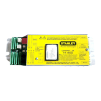
MC521 PRO Control Box
10.21.2015
1.800.7.ACCESS • www.stanleyaccesstechnologies.com • Document # 204066 REV D2 15
Copyright 2015, Stanley Security Solutions. All rights reserved. Reproduction in whole
or in part without the express written permission of Stanley is prohibited.
Attachment 1
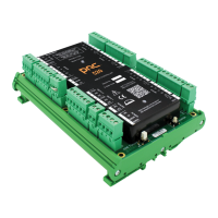
MC521 Pro Controls and Indicators
(Sheet 2 of 2)
ITEM CONTROL/INDICATOR DESCRIPTION
1 Motor 2 Connector P402 Motor No. 2 connector.
2 Power Connector J500
Connecon point for incoming line, neutral, and common
power wiring.
3 Fuse F500 Controller fuse-- 5 Amp, 250V
4 Motor 1 Connector P401 Motor No. 1 connector.
5 Terminal Block Connector TB1 Connecon point for solenoid lock control.
6 Terminal Block Connector TB2 Connecon point for funcon switch (rotary or rocker).
7 Terminal Block Connector TB6
Includes spare I/O and AUX DC supply. Do not populate TB6 unl
further noce.
8 Encoder 2 Connector J301 Not used.
9 Two Digit Display
Displays Controller Status. Also serves as the display for tune-in
by pushbuon switches and indicates encoder movement.
10 Encoder 1 Connector J300 Connecon point for motor encoder No. 1.
11 Up Pushbuon Switch SW300 Used manual setup and tuning of door when PDA is not available.
12 Down Pushbuon Switch SW301
Used for manual setup and tuning of door when PDA is
not available.
13 Enter Pushbuon Switch SW302
Used for manual setup and tuning of door when PDA is
not available.
14 COM1 Jack RS232 COM1 connector. Connecon point for PDA harness.
15 COM2 Jack RS232 COM2 connector. Not used.
16 Terminal Block Connector TB7
Includes RS485 and AUX DC supply. Do not populate TB7 unl
further noce.
17 Terminal Block Connector TB5
Connecon point for side-screen sensor and closed-posion
switch.
18 Terminal Block Connector TB4
Connecon point for inside sensor, outside sensor and
push plate.
19 Terminal Block Connector TB3
Connecon point for Stanguard, doorway holding beam, and
breakout switch. Using jumper wires across TB3 terminals 1 to
5 and 2 to 6, internal transformer supplies power to mulple
external sensors.