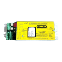
MC521 PRO Control Box
4 Document # 204066 REV D2 • www.stanleyaccesstechnologies.com • 1.800.7.ACCESS
Copyright 2015, Stanley Security Solutions. All rights reserved. Reproduction in whole
or in part without the express written permission of Stanley is prohibited.
10.21.2015
Connecting Main Power Wiring
Warning: To prevent injury to personnel, incoming electrical power to the header must be deenergized before
connecng electrical service to the control box.
Warning: All electrical wiring must conform to Naonal Electrical Code Requirements.
1. DEENERGIZE incoming electrical power to header.
2. Refer to Aachment 2, and, using wire nuts, CONNECT incoming line, neutral, and ground wires
to the controller power harness.
3. IF adhesive wire clamps will be used, DEGREASE metal surfaces on inside of header cover
where clamps will mount.
4. SECURE wiring to top of the header track tube, and ENSURE the following:
• All wires are clear of belts and belt brackets.
• Header cover opens and closes without interference.
Connecting Accessories (As Applicable)
Refer to Aachments 2 and 3, and CONNECT any of the following subsystems to the MC521 Pro Controller:
• Funcon switch (rotary, rocker and “POWER” switch wiring)
• Stanguard threshold sensor
• Doorway holding beam
• Breakout switch
• Solenoid lock
• SU-100 moon sensor(s) wiring (refer to Stanley Document #203957)
• OA-203C presence sensor(s) wiring
• Push plate wiring
• Door posion switch closed contact (with door closed)
• Stanvision
TUNE-IN INSTRUCTIONS
Warning: The door path must be free of objects and remain clear unl the First Install Sequence (FIS) is complete.
During this sequence the sensors are inacve and the door has no SAFETY. To stop the door, turn power off or put
the doors into breakout.
NOTE:
1. Tune In: The MC521 Pro Controller can be tuned-in using a handheld device or using the pushbuon switches
located on the controller. Tune-in using a handheld device is the preferred method.
2. Status Codes: During normal operaon, the digital display indicates status codes. The “UP” and “DOWN” push-
buon switches can be used to enter and display data values. The user interface values are shown in Tables 2
through 4.
4