– 4 –
PARTS REPLACEMENT
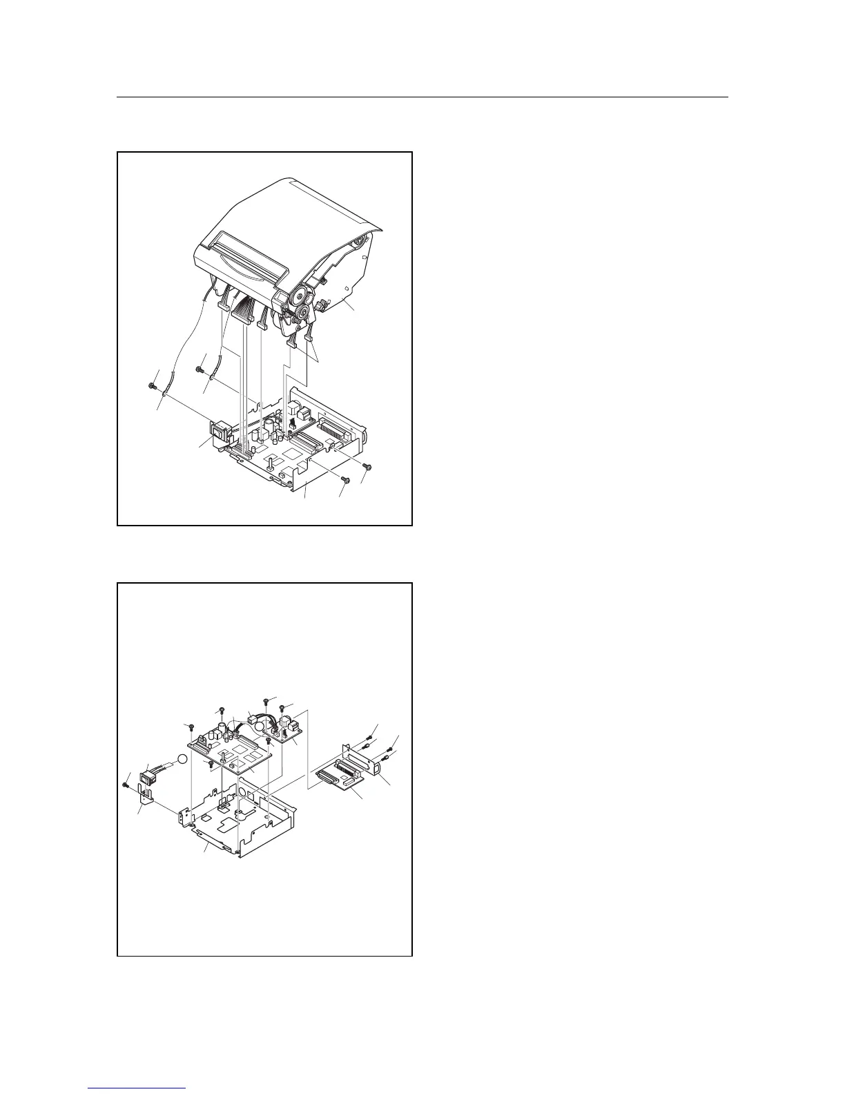
3. Board Chassis Unit
(1) Turn off the power switch1, disconnect the power
cord from the wall outlet.
(2) Remove
• Upper case according to the procedure described
in item 2.
• Three screws 2
• Screws 3
• Two wires 4
• Six connectors 5
• Printer mechanism 6
• Board chassis unit 7
4. Main Logic Board
(1) Turn off the power switch, disconnect the power
coard from the wall outlet.
(2) Remove
• Board chassis unit according to the procedure
described in item 3.
• Two screws 1
• Two screws 2
• Sub chassis 3
• Interface board 4
• Two screws 5
• Two connectors 6
• Power switch 7
• Sub-board 8
• Four screws 9
• Main logic board 0
• Screw A
• Switch holder B
• Board chassis C
2
2
2
3
1
5
4
6
4
7
9
9
5
5
8
C
B
A
7
6
6
A
A
9
9
0
3
2
1
4
1
2
 Loading...