Do you have a question about the Star DP8340 SERIES and is the answer not in the manual?
Checks if all necessary accessories are included after opening the box.
Install the Paper Holders in the outermost holes in the rear of the printer.
Important operational guidelines, safety precautions, and maintenance tips for the printer.
Details and illustration of the printer's power supply unit.
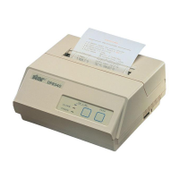
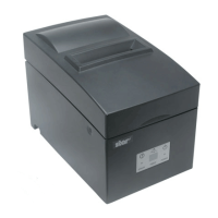
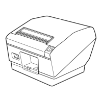
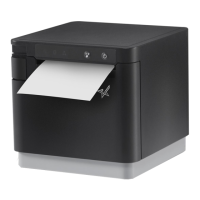
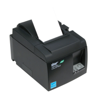
Illustrations of the printer's front and rear views, identifying key components.
Detailed explanation of the function of each part of the printer.
Step-by-step guide for installing the ink ribbon into the printer.
Instructions for safely removing the ink ribbon from the printer.
Procedure for inserting roll paper into the DP8340F model printer.
Guide for inserting sprocket-feed paper into the DP8340S model printer.
Instructions for removing paper from the printer after printing.
Defines synchronization, baud rate, word length, parity, stop bits, and signal polarity.
Diagram showing the input and output circuits for the RS-232C interface.
Configuration guide for setting DIP switches on the printer for various functions.
Details pin assignments, signal names, direction, and functions for modular jack connectors.
Provides examples and diagrams for connecting the printer to a host computer.
Explains the circuit for driving external peripheral units like paper cutters.
Instructions for connecting peripheral unit cables to the CN3 connector.
Details the absolute ratings and drive output specifications for the peripheral circuit.
Lists control codes used for managing the peripheral drive circuit.
Defines synchronization, baud rate, word length, parity, stop bits, and signal polarity for D-Sub.
Diagrams illustrating the RS-232C and Current Loop interface circuits.
Guide for configuring DIP switches for the D-Sub 25 pin interface.
Instructions for adjusting jumpers on the control board for interface configuration.
Details pin assignments, signal names, direction, and functions for D-Sub 25 pin connectors.
Provides an example connection diagram for the D-Sub 25 pin interface to an IBM PC.
Explains the circuit for driving external peripheral units for the D-Sub interface.
Instructions for connecting peripheral unit cables to the CN3 connector for D-Sub.
Details absolute ratings and drive output for the peripheral drive circuit.
Lists control codes for managing the peripheral drive circuit for D-Sub interface.
Controls data transfer using the DTR line as a busy flag for the printer.
Manages data flow using X-ON/X-OFF signals to control buffer status.
Ensures data integrity during transmission using STX/ETX and parity checks.