17
DATA Outputs
Data I/O Connector
The indicator has an 8 pin data I/O connector with several supported communication protocols.
These communication protocols can be accessed using a dedicated cable or through custom wiring
using the Pigtail cable.
Serial ASCII Command Protocol (USB/RS232/UART)
The gage supports several "serial" interfaces that interact with the device using a human readable
ASCII command protocol. This protocol can be accessed over USB as a virtual com (CDC) device,
RS232 or TTL level UART. For all hardware implementations, the specifications and command set
are identical.
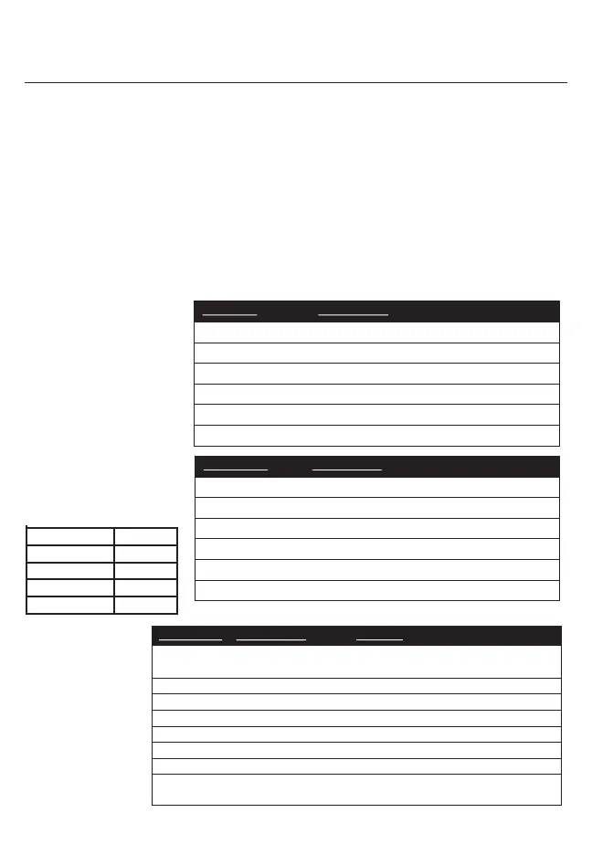
Baud
9600
Data Bits
8
Parity
None
Stop Bits
1
Flow Control
None
Hardware Specifications
Commands
All Commands are terminated
with a new line character
<CR>. All commands and the
most common settings are
listed below. Please see
technical manual for more
details.
Examples: Enter p013=2
followed by a <CR> to change
the display units to MM.
COMMAND DESCRIPTION
R Print current gage reading
C Clear gage
H Toggle Hold Mode
rstERR Resets errors
?pXXX Get the value of configuration parameter "XXX"
pXXX=<new value> Set the value of parameter "XXX" to <new value>
RESPONSES DESCRIPTION
+ 2.1380, MM 13 character response to print reading
SUCCESS Parameter is successfully written to
NOT FOUND Parameter Name could not be found
NO ACCESS User does not have write access
OUT OF BOUNDS New value is not within the allowable range
NON NUMERIC New value is not a number
PARAMETER DESCRIPTION OPTIONS
P007 Gage Resolution 1 = .001", .02mm, 2 = .0005", .01mm,
3 = .0001", .002mm, 4 = .00005", .001mm
P011 Measurement Mode 0=ABS, 1=TIR, 2=INCR
P013 Units
1=Inches, 2=Millimeters
P019 Travel Reverse 0=Normal, 1=Reverse
P021 Hold On 0=Off, 1=On
P022 Hold Mode 0=Frz, 1=Min, 2=Max
P040 Ratio On 0=Off, 1=On
P063 Suppress Output 0=None, 1=Disable error and status
responses