unit can be mounted to the wall using the mounting rails on the back of the unit..
.3 Cable Termination to the iSTS
screws on the protection panel on the front of the unit and the terminal cover panel on either the top
of the unit. Holes should be cut through the terminal cover plate to allow cables to be fed through to
. Feed cables through the holes before attaching lugs.
terminals will accommodate a standard M8 cable lug. The maximum cable size (using narrow palm lugs)
mm² / AWG 00 / 0.1 in². Ensure that the cables are supported to prevent putting strain on the terminals.
the connections are tight before replacing the cover.
When working on live iSTS, be sure to comply with the applicable national accident prevention rules.
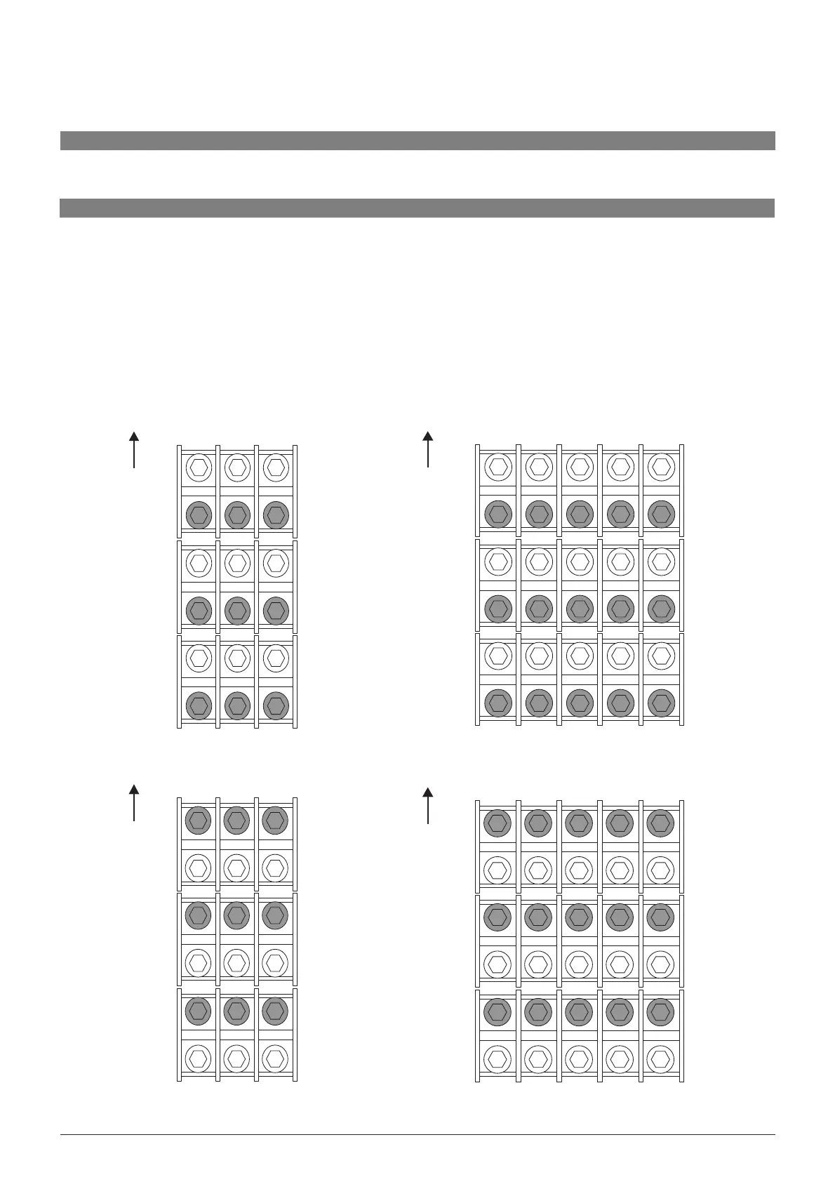
Single-Phase Top Entry Model
NeutralActiveEarth
Top of unit
Supply 1
Supply 2
Output
Single-Phase Bottom Entry Model
Neutral Active Earth
Top of unit
Supply 1
Supply 2
Output
Neutral
Three-Phase Top Entry Model
Line 1Line 2Line 3Earth
Top of unit
Supply 1
Supply 2
Output
Neutral
Three-Phase Bottom Entry Model
Line 1 Line 2 Line 3 Earth
Top of unit
Supply 1
Supply 2
Output