.3 Reinstatement from Maintenance Bypass
1. Turn on both Supply 1 and Supply 2 circuit breakers located at the front of the unit. Wait for the unit
start up. The mimic on the display screen should show Supply 1 and 2 as GREEN to indicate that
supplies are active in the STS.
2. Move or operate the Preferred Source selection switch to the supply that is in bypass.
3. Check the mimic LEDs and ensure that the STS and the maintenance bypass LEDs are the same (GREEN).
4. Finally operate the bypass switch, returning it to the middle position.
5. The unit will now be normal operation mode.
to the LAN interface can be done two different ways with a RJ45 Cat5 Ethernet cable:
▪ To a Network hub/switch using a straight-through cable.
▪ To a PC using a cross-over cable (most PCs can now work with a straight-though cable).
.1 Connection to a Network
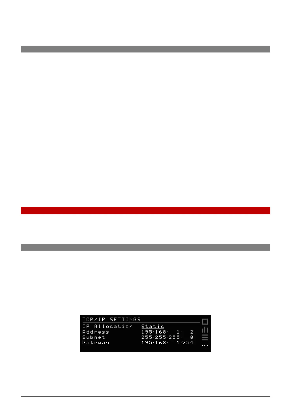
default the STS uses s Static default IP address of 192.168.1.2, however, if required from the display or
interface a DHCP can be selected to have the IP information assigned automatically after the Ethernet
plugged in at both ends, this process can take up to several seconds to complete. If your network does not
DHCP server or if you wish to use a static IP, you can change the IP Allocation on the Communications
shown below (or the Control Panel page on the Web server).
navigation buttons on the unit and move to the Settings menu, enter the passcode 1 2 3 to access
. Setting IP Allocation to Static allows for manual input of IP address, subnet and gateway.
COMMUNICATION SETTINGS