.6 Confirm Operation
1. Press the Preferred Button to highlight ‘I’ on the Preferred Indicator. Wait for the STS to transfer to
1, if is not already on Supply 1. On Supply 1 LED will turn green.
2. Turn off Supply 1. Confirm that the STS transfers to Supply 2. On Supply 2 LED will turn green.
3. Turn on Supply 1. Confirm that the STS automatically transfers to Supply 1 after a 3 second delay.
Supply 1 LED will turn green.
4. Press the Preferred Button to highlight ‘II’ on the Preferred Indicator. Wait for the STS to transfer to
2. On Supply 2 LED will turn green.
5. Turn off Supply 2. Confirm that the STS transfers to Supply 1. On Supply 1 LED will turn green.
6. Turn on Supply 2. Confirm that the STS automatically transfers to Supply 2 after a 3 second delay.
Supply 1 LED will turn green.
7. The operational test is complete. You can now select a preferred supply if any.
Bypass mode allows the load to be connected to one supply without going through the
maintenance bypass switch is located either at the top or the bottom of the enclosure. The switch is
the “N” position and can be used to bypass the internals of the STS to either “Supply Source 1” or
THE MAINTENANCE BYPASS SWITCH SHOULD ONLY BE USED TO SELECT THE PRESENTLY OPERATING SOURCE.
IT CANNOT BE USED TO TRANSFER THE CRITICAL LOAD FROM ONE SOURCE TO THE OTHER.
The maintenance bypass switch utilises make-before-break switching, incorrect operation of the
maintenance bypass features could result in dangerous voltages occurring and short circuits.
: A padlock can be used to stop inadvertent or unauthorized operation of the switch.
.2 Maintenance Bypass Procedure
Mode on Supply 1
1. Use the TRANSFER pushbutton on the front of the unit to transfer the load to Supply 1.
2. TURN OFF Supply 2 using the isolator switch on the front of the unit.
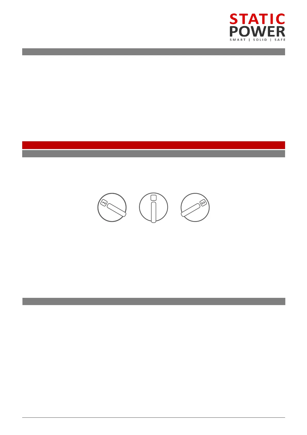
3. Finally operate the Maintenance Bypass Switch rear by turning to position 1. The unit will now be in
Mode on Supply 2
1. Use the TRANSFER pushbutton on the front of the unit to transfer the load to Supply 2.
2. TURN OFF Supply 1 using the isolator switch on the front of the unit.
3. Finally operate the Maintenance Bypass by turning to position 2. The unit will now be in bypass mode
Supply 2.
N
Normal Source 2Source 1