41
734.843 | 10.48
EN
5 Operating the StecaGrid
5.1 Operation and fault display via an LED
The front of the control unit is equipped with an LED which shows the operating
status of the inverter(s). During startup, the LED lights up green (dimmed). Star-
tup begins with a series of test procedures (which take a few seconds). When
the output of the solar modules is high enough, the inverter will switch to 'active
mode'. When there is little irradiation it may be that the solar modules do not
produce enough power to feed into the power grid.
The message then appears on the display: 'Standby'
An overview of the other messages and the corresponding LED status can be
found in table 1.
LED status System status Explanation, cross-references
Green – dimmed Sleep mode The system is switched to energy-saving
mode (night shut-off).
Green Active mode The system is running (normal operation
status)
Green – flashing
Standby mode The system can supply energy.
Red – flashing
Partial active There is a fault in one of the inverters
(the others are still supplying energy).
The fault message can be called up over
the display.
Red Error The inverter has a fault (no energy is be-
ing supplied). The fault message can be
called up over the display.
Off Off There is no grid voltage present.
Table 1: Overview of the LED messages
The main menu
The display is used to specify (new) settings as well as showing system data.
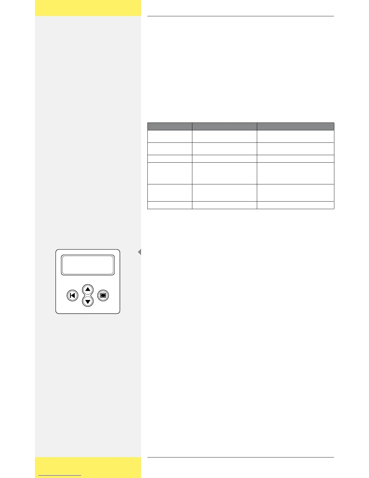
Navigating the display
Button (A) Escape:
Use this button to return to the main menu from the individual menu
items and to exit the setup menu.
Buttons (B) and (C) Arrow buttons Up and Down:
Use these buttons to run through the individual menu items or to carry
out settings in the setup menu.
Button (D) Enter:
Use this button to go to another menu level or to confirm a setting in
the setup menu.
Depending on the user profile set, 9 menus can be called up by pressing the Up
or Down button.
User profiles can be set on 3 levels.
Basic [Submenu: 1-2-5]
Advanced [Submenu: 1-2-3-5]
Service [Submenu: 1-2-3-4-5]
Depending on the options implemented, submenus 7 and 8 can still be added.
Using this menu structure, a user can call up all necessary data.
You will find below an overview of the functions with a short description. There,
in the left-hand column, a figure is shown. This figure also appears in the top
right of the display and shows the location and selected menu or function. If, for
example, the location of a menu item is shown as 5-3-3, this means that, in the
main menu, menu 5 (settings) must first be chosen. Then, submenu 3 (language)
is selected. The third item is then 5-3-3 (German). In this example, the language
shown on the display can be changed to German by pressing the Enter button
here.
•
•
•
A D
B
C