21
For Example: 250
o
F = (250
o
F/20Ma - 4 mA) 20mA + b
-62.5 = b (”
”)
Retransmission Of
Process Variable
The M2B is capable of re-transmitting the process output “
'
''
'
” or the set
point input “
” via a 0-20mA analog signal. If a 4 to 20mA output is
desired, follow the scaling calculation outlined in the remote set point
section. Insert the low and high values for “
” and “
”.
Second Set Point
Input
The M2B is provided with a secondary set point “
” pre-programmed for
0
o
F (-17.7
o
C), but is adjustable. When an external switch contact is closed,
the controller will switch to this set point and will display “
” . This will
occur when SP2 is set to 0
o
F and the actual setpoint is any other value.
The controller will revert to “
” when the contact is released and unit
returns to run mode.
Flow Meter
The M2B is capable of displaying and alarming process flow in gallons per
minute (GPM) or liters per minute (LPM), via a factory installed flow sensor.
The M2B is capable of accepting numerous flow sensors.
Note:
Please contact the factory if the flow readout oscillates or appears
erratic for evaluation, calibration, and installation instructions.
The M2B is equipped with a software activated digital filter. The filter is
adjustable from 0-100, the larger the number the greater the signal
dampening. Consult the factory for further information and access.
Remote
Thermocouple
Monitor
Monitors type “J” thermocouple input. Depress
INDEX
key until “
)
))
)
”
appears. Temperature is displayed in process display window. See Figure-1
for location.
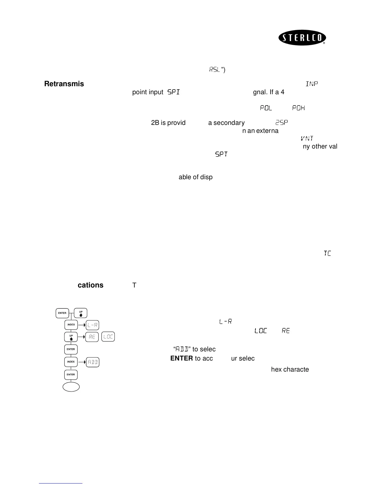
Communications
The Sterling M2B controller can communicate with a host machine via a
half or full duplex RS232 or RS485 communication link.
• Press and hold the
UP
and
ENTER
keys to access the secondary
menu.
• Use the
INDEX
key until “
+
++
+
” appears.
• Use the
UP
or
DOWN
keys to select “
” or “
”
.
• Depress
ENTER
to accept your selection.
•
INDEX
to “
” to select the controller address “1 to 3FF”.
• Depress
ENTER
to accept your selection.
Note
: All data is sent and received in the ASCII hex character format, using
10 bits: 1 Start bit, 8 data bits, no parity and 1 Stop bit.
Any changes in the communication protocol should be made by qualified
technicians.
Host
will be used to describe the computer operating as the originator of
communications.
Instrument
will be used to describe the process
control(2) using this protocol. In the following examples, only
Host
and
Instrument
will be used.
P
S
S
S
RUN