7
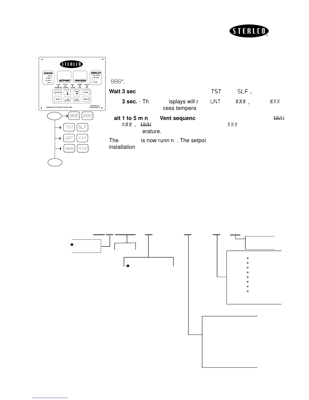
Quick Start Instructions for the M2B Controller
The quick start instructions can only be used provided the M2B is properly
installed and wired.
Turn unit on
- The “
SETPOINT
” and “
PROCESS
” LED displays will read
“
“.
Wait 3 sec.
- The LED displays will read “
“ and “
“
Wait 3 sec.
- The LED displays will read “
“and “
“
where “
“
equals the current process temperature.
Wait 1 to 5 min. for Vent sequence.
- The LED displays will read “
“
and “
“
“
“ equals the process setpoint. “
“ equals the current
process temperature.
The process is now running. The setpoint may now be adjusted for your
installation. Press
SETPOINT
. Use
ARROW
to adjust.
Model Identification
To determine the options that are included with the M2B, use the following
configurator. The character “X” represents an option that is included.
∆
ON
3 sec.
S
P
S
P
S
P
3 sec.
1 to 5
min.
S
P
RUN
Options
0 - STD.
1 - RS485 SPI
2 - RS485 GEN
3 - 4-20 Heat Out
4 - 4-20 Cool Out
5 - 4-20 Heat/Cool
6 - RS232 GEN.
7 - Process Input
4-20 MA S.P. & P.V. XMIT
Temp Limit
0 - 250 F
1 - 180 F
2 - 200 F
3 - 450 F
4 - 300 F
5 - 400 F
6 - 550 F
7 - 650 F
8 - Chiller
Base
00521
601
Special Options
= STD
1="J" T/C
2=Flow
3=RAMP/SOAK (Null)
4=Process Input
4-20 MA S.P. & P.V. XMIT
5=2 Stage Set Point (Null)
6=4-20 Heat Out
7=4-20 Cool Out
= STD
R = Rebuilt
XXXX
XXX
030 (30 gpm)
075 (75 gpm)