Do you have a question about the Sterlco M2B and is the answer not in the manual?
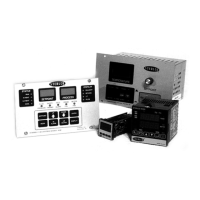
Overview of the M2B controller's design and capabilities for process control.
Explains how to interpret the M2B controller model number and options.
Guidelines for proper installation location and conditions for the controller.
Precautions and recommendations for power supply and electrical noise.
Information on accessing and changing security levels and passwords.
Descriptions of the status and indicator lights on the M2B controller.
Details on various alarm conditions and their behavior on the M2B controller.
Explains the function of each key on the M2B controller's input keypad.
Describes the auto vent sequence and its display indication.
Step-by-step guide to start the autotuning process for process optimization.
Pre-determined parameters for quick PID tuning response.
Introduction to the 16-segment programmable Ramp/Soak feature.
Explains the M2B controller's approach to programming ramps and soaks.
How to configure and use the remote set point input option.
Procedure for toggling set point between local and remote input.
Details on using a secondary set point for process control.
Information on displaying and alarming process flow rates.
How to monitor thermocouple inputs on the M2B controller.
Capabilities and links for host machine communication via RS232/RS485.
Explains error messages that may be reported by the instrument.
A table listing possible error codes and their meanings.
Lists and describes commands for the SPI communication protocol.
Detailed explanations of the SPI protocol command functions.
Steps to reset common fault conditions on the M2B controller.
Procedure to audit the accuracy of temperature probes.
Details on accessing parameters using home (index) keys.
Explains the on/off control action and its characteristics.
Describes the proportional control action and its proportional band.
Details the integral action for compensating offset errors.
Explains derivative action for minimizing overshoot.
Function that inhibits integral action to prevent overshoot.
Explains direct and reverse actions for heating and cooling applications.
Adjusting gain and proportional band for controller responsiveness.
Adjusting integral time to correct for offset errors.
Explains derivative time's effect on process disturbances.
Defines alarm conditions based on process variable setpoints.
Alternative control conditions selectable within the controller.
Compensates for differences between sensor and measured temperature.
Band above/below setpoint with no output action in on/off control.
Slowly adjusts proportional band to eliminate offset error.
Input not changing or responding properly to output action.
Explains the two-state (on/off) output behavior.
Controller modulates output power using PID parameters.
Proportionality of output to error between setpoint and process value.
Controller setpoint moves linearly over a fixed period.
Facility for performing 'on' and 'off' sequences for optimization.
Time entered into a program where setpoint remains constant.
| Voltage | 120/240 VAC |
|---|---|
| Display | LED |
| Control Output | Relay |
| Power Supply | 100-240V AC, 50/60Hz |
| Operating Temperature | 0-50°C |