55
08/13424999756
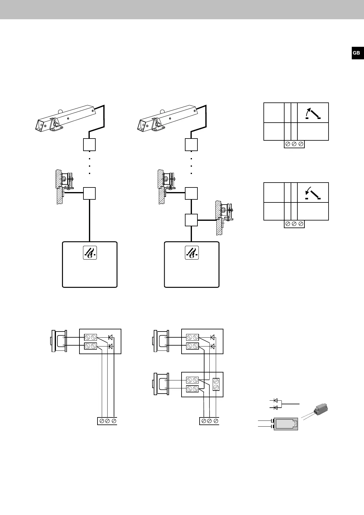
Connecting diagram magnetic clamps / magnetic locking
All work to be carried out without mains supply (230 V AC) or any batteries connected. Route the connecting cables into
the control panel housing at the top. Connect all connecting cables according to the wiring diagram and make sure that
theyarecorrectlyconnected.Incorrectconnectionsorgureorcolourmix-upscanleadtoincorrectfunctionofthecon-
trol panel or of the external components. The notes and installation directives in the technical documentation are always
to be observed.
Compact control panel 4A, 4A/M und 8A, 8A/M
See Page 63, DIP switch 3 ON
1 2 3
+
-
1 2 3
+
-
+
-
-
+
-
+
-
+
O V DC
24 V DC + -
1
2
1 2 3
O V DC
24 V DC + -
1 2 3
Magnetic locking*
Magnetic clamp*
Magnetic locking**
Magnetic clamp*
1
Opening via spring force of
the gas spring
2
Closing via spring force of the
door closer
The door is kept
open by magne-
tic clamp
Window
closed
several magnetic clamps /
magnetic lockings
Junction box
Junction box
Magnetic clamp
Monitoring diodes
Last magnetic clamp
Magnetic clamp 1
one magnetic clamp/
magnetic locking
 Loading...