59
08/13424999756
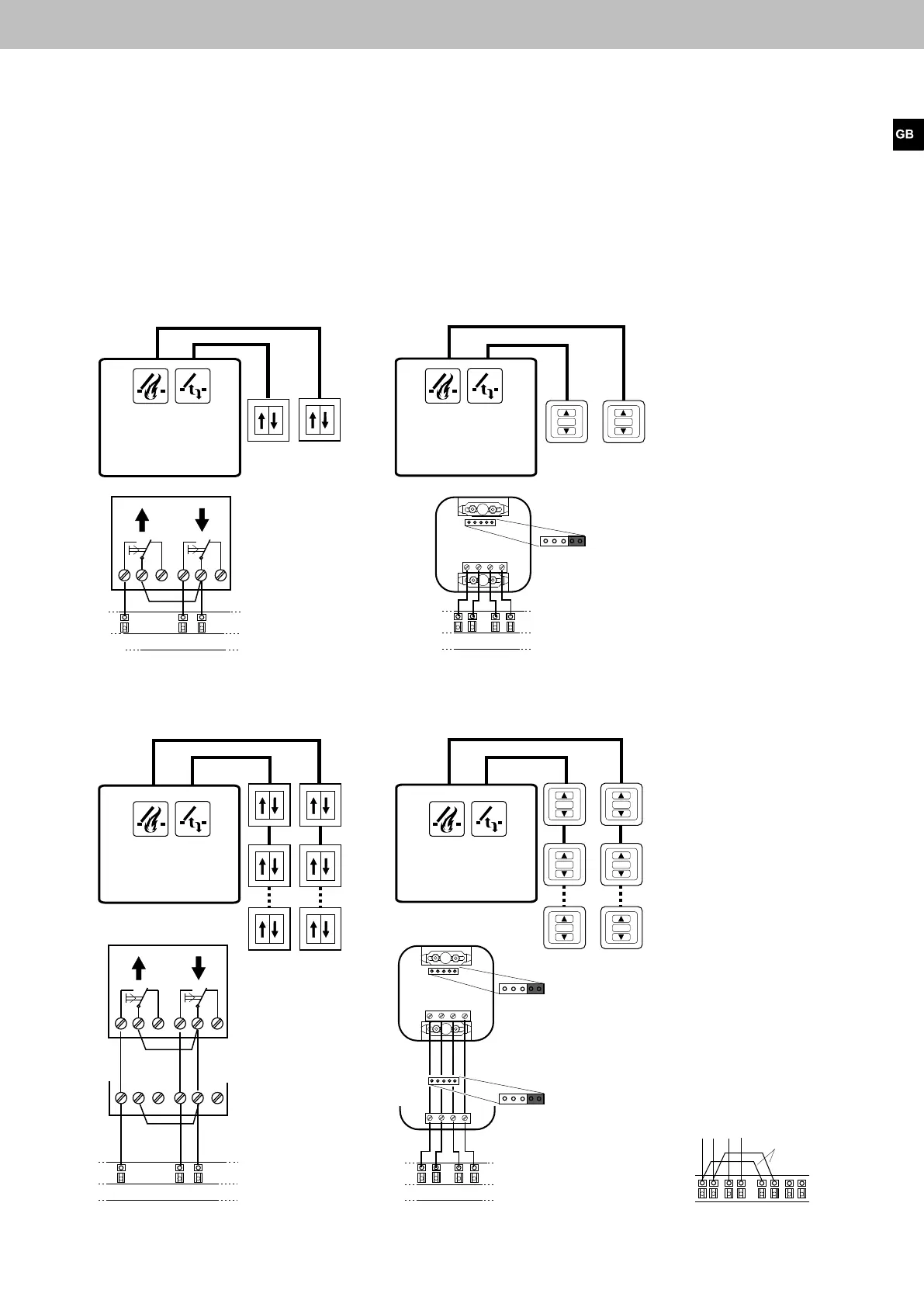
Connecting diagram vent switch
All work to be carried out without mains supply (230 V AC) or any batteries connected. Route the connecting cables into
the control panel housing at the top. Connect all connecting cables according to the wiring diagram and make sure that
theyarecorrectlyconnected.Incorrectconnectionsorgureorcolourmix-upscanleadtoincorrectfunctionofthecon-
trol panel or of the external components. The notes and installation directives in the technical documentation are always
to be observed.
one vent switch LTA11 per
ventilation group
one vent switch LTA25 per
ventilation group
SS
P
P
O
O
15 16 18
19 20 22
15 16 17 18
3 2 1 4
STOP STOP
19 20 21 22
SS
P
P
OO
SSPP
O
O
15 16 18
19 20 22
STOP
STOP
15 16 17 18
19 20 21 22
3 2 1 4
3 2 1 4
STOP
STOP STOP
STOP
1718
19 20 2122
15
16
Compact control panel 4A, 4A/M und 8A, 8A/M
Jumper
Group 1 Group 2
Group 1
Group 2
Group 1 Group 2
Group 1
Group 2
several vent switches LTA11 per
ventilation group
several vent switches LTA25 per
ventilation group
Jumper
Jumper
last vent
switch
Group 1
last vent
switch
Group
2 2
Group 1
Group 2
last vent
switch
Group 1
last vent
switch
Group 2
Group 1
Group 2
Bridge
Allocation vent switches
Ventilation group 1 affects motor
circuit 1, ventilation group 2 affects
motor circuit 2.
Connection variant: ventilation
group 1 affects both motor circuits
(1+2)..
Other connections possibilities
please see Technical Documenta-
tion of LTA25 or LT11..
 Loading...