56
08/13424999756
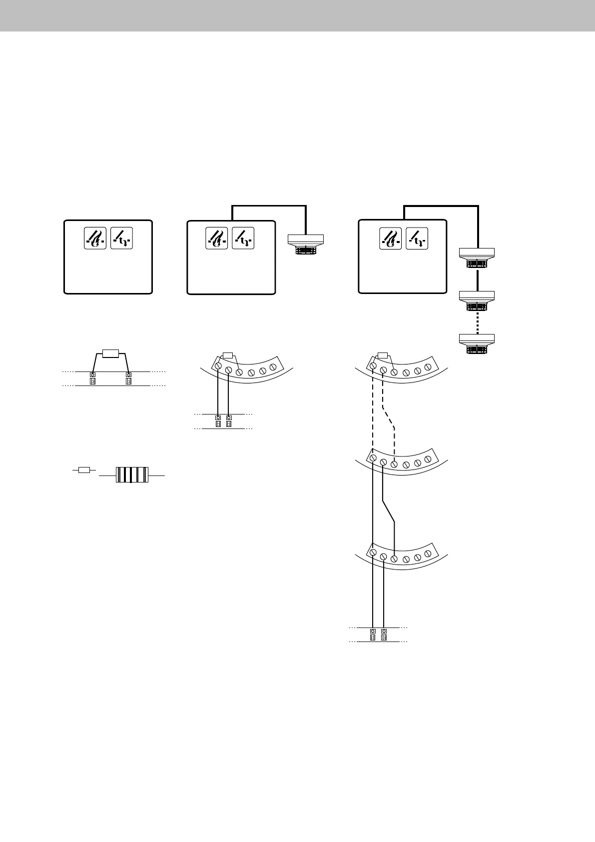
Connecting diagram smoke detector
All work to be carried out without mains supply (230 V AC) or any batteries connected. Route the connecting cables into
the control panel housing at the top. Connect all connecting cables according to the wiring diagram and make sure that
theyarecorrectlyconnected.Incorrectconnectionsorgureorcolourmix-upscanleadtoincorrectfunctionofthecon-
trol panel or of the external components. The notes and installation directives in the technical documentation are always
to be observed.
Compact control panel 4A, 4A/M und 8A, 8A/M
10kΩ
7 8
1
2
3
4
5
6
1
2
3
4
5
6
1
2
3
4
5
6
10kΩ
1
2
3
4
5
6
10kΩ
7 8
7 8
10kΩ
1 2
3 4
5
without smoke detector one smoke detector several smoke detectors
SSD 521
UTD 521
UTD 523
MSD 523
last smoke detector
SSD 521
UTD 521
UTD 523
MSD 523
one smoke
detector
1.smoke detector
last
smoke
detector
2. smoke
detector
1. smoke
detector
Monitoring resistor
Color marking:
1. Ring: brown
2. Ring: Black
3. Ring: Black
4. Ring: red
5. Ring: brown
 Loading...