12 | WPL basic | WPL S basic www.stiebel-eltron.com
INSTALLATION
Mounting
Note
Suitable appliances for water softening and desalinating,
as well as for charging and flushing heating systems, can
be obtained via trade suppliers.
Note
If you treat the fill water with inhibitors or additives, the
same limits as for desalination apply.
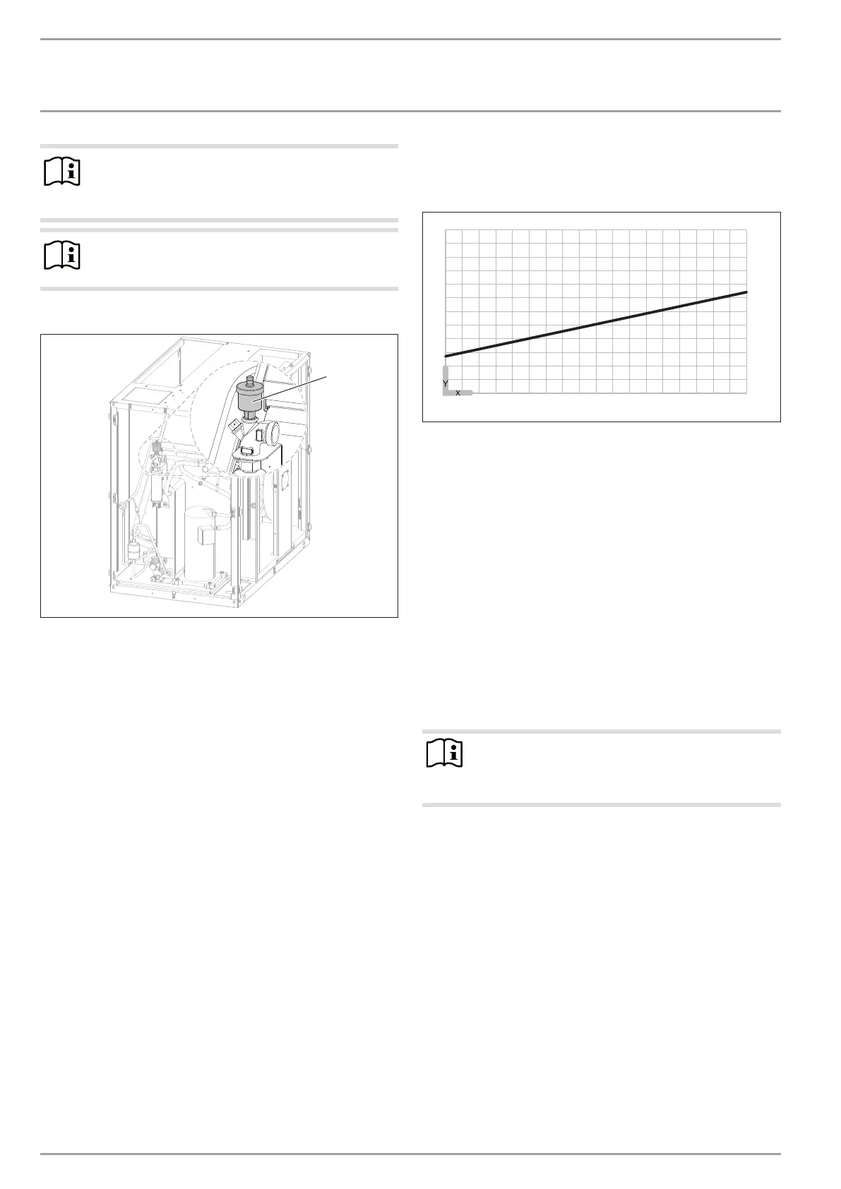
Venting the heating system
1
26�03�01�1638�
1 Air vent valve
Vent the pipework carefully. For this, also activate the air
vent valve integrated into the heating flow inside the heat
pump.
10.4 Flow rate, heating side
10.4.1 Minimum flow rate for operation without a buffer
cylinder
The appliance is designed in such a way that no buffer cylinder
is required to provide hydraulic separation of the flow in the heat
pump circuit and the heating circuit in conjunction with space
heating systems.
In an installation with several heating circuits, we recommend
using a low loss header.
The minimum flow rate is set via the temperature differential of
the heating system.
Set the heating circuit pump so that the value is equal to or lower
than the maximum temperature differential.
The setting is made in heat pump operation alone. For this, the
following settings must be carried out first:
Temporarily remove the fuse from the electric emergency/
booster heater to isolate it from the power supply. Alterna-
tively, switch OFF the second heat source.
Operate the heat pump in heating mode.
Minimum flow rate with single room control via FE7orFEK
Maximum temperature differential on the heating side with over-
flow valve or single room control with remote control
-15 -10 -5 0 5 10 15 20 25 30
0
2
4
6
8
10
12
84�03�01�0172
X Outside temperature [°C]
Y Maximum temperature differential [K]
In this case, one or more heating circuits in the heating system
must be left open. The open heating circuit(s) should be installed
in the lead room (room in which the remote control is installed,
e.g. the living room). Single room control can then be carried
out with the remote control or indirectly by matching the heating
curve.
Fully open the heating circuit(s) in the lead room.
Close all other heating circuits.
If an overflow valve is installed in the heating system, close
this fully before determining the minimum flow rate.
Make the settings at the circulation pump when the tempera-
ture differential between the flow and return temperature
has stabilised.
Set the heating circuit pump so that the minimum flow rate re-
quired to operate the system is safeguarded.
Note
Never adjust the flow rate of the cylinder primary pump.
The flow rate of the cylinder primary pump has been
optimised at the factory.
Compare the resulting temperature differential between the
flow and return at the appliance with the diagram “Maximum
temperature differential on the heating side with overflow
valve or single room control with remote control”.
Set the heating circuit pump so that the value is equal to or
lower than the maximum temperature differential.