www.stiebel-eltron.com WPL basic | WPL S basic | 21
INSTALLATION
Commissioning
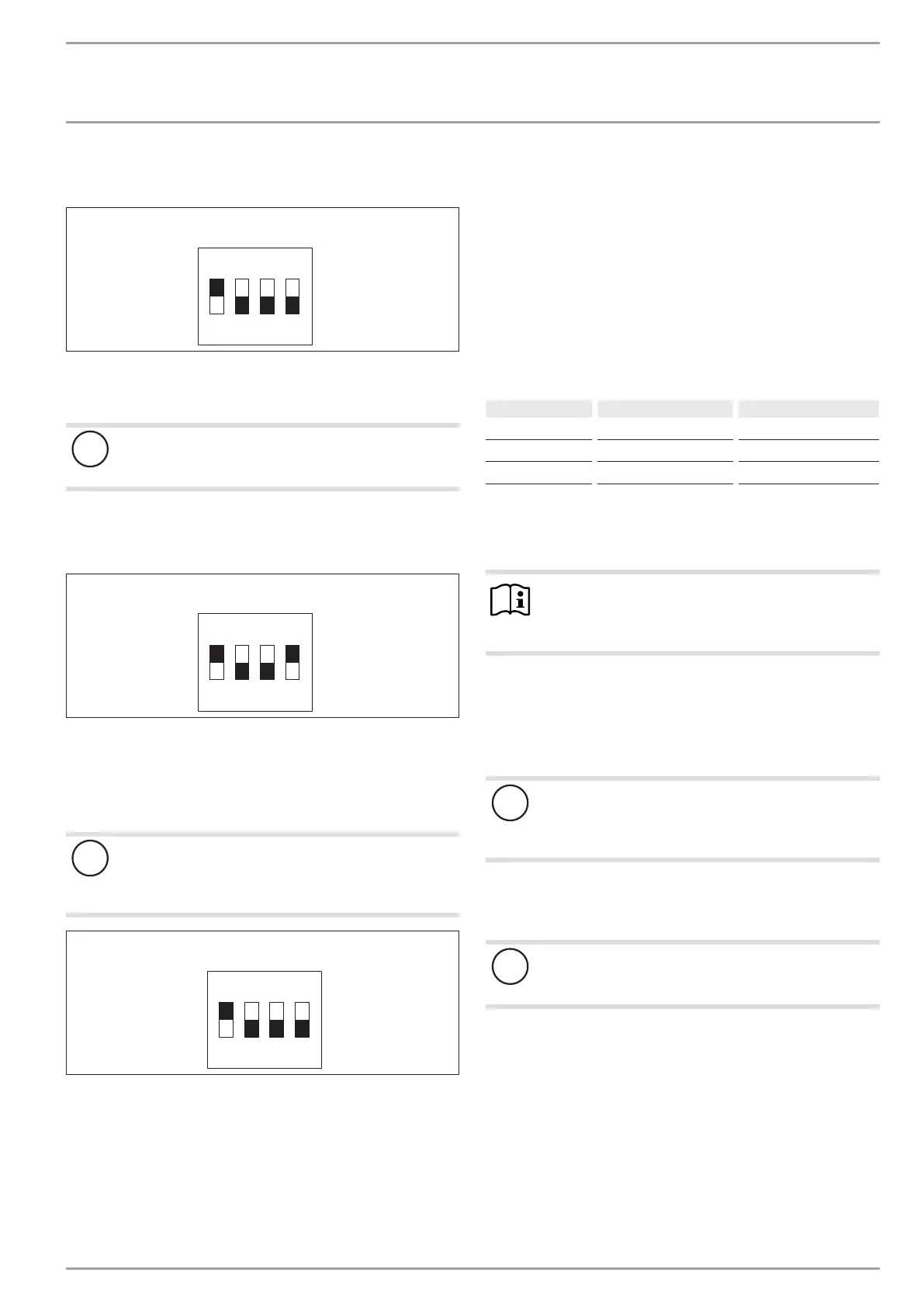
Factory setting:
Compressor mode with electric emergency/booster heater
WP - Typ
ON
1 2 3 4
D0000057054
Check whether the DIP switch is set correctly.
Compressor mode with external second heat generator
!
Damage to the appliance and environment
In this case, do not connect the electric emergency/
booster heater.
If the appliance is operated in dual mode operation with an ex-
ternal second heat generator or as module with another identical
heat pump, set the DIP switches as follows:
WP - Typ
ON
1 2 3 4
D0000057055
DIP switch (BA)
With the DIP switch (BA), the operating mode of the heat pump
is set.
Check whether the DIP switch is set correctly.
!
Damage to the appliance and environment
DIP switches 2, 3 and 4 must always be set to the OFF
position. The heat pump can only be operated when the
switch is in this position.
BA
ON
1 2 3 4
D0000057050
12.3 Settings
12.3.1 Heating curve adjustment
The efficiency of a heat pump decreases as the flow temperature
rises. The heating curve should therefore be adjusted with care.
Heating curves that are set too high cause the zone valves and
thermostatic valves to close, which may lead to the minimum flow
rate required for the heating circuit not being achieved.
Observe the WPM operating and installation instructions.
The following steps will help you to adjust the heating curve cor-
rectly:
- Fully open thermostatic or zone valves in a lead room (e.g.
living room and bathroom).
We do not recommend installing thermostatic or zone valves
in the lead room. Control the temperature for these rooms
via remote control.
- At different outside temperatures (e.g. –10°C and +10°C),
adjust the heating curve so the required temperature is set in
the lead room.
Standard values to begin with:
Parameter
Underfloor heating system
Radiator heating system
Heating curve 0.4 0.8
Control response time
5 15
Comfort temperature
20°C 20°C
If the room temperature in spring and autumn is too low (approx.
10 °C outside temperature), the value of parameter COMFORT TEM-
PERATURE must be raised in the heat pump manager menu under
SETTINGS / HEATING / HEATING CIRCUIT.
Note
If no remote control is installed, raising the parameter
“COMFORT TEMPERATURE” leads to a parallel offset of
the heating curve.
Increase the parameter “heating curve” if the room temperature
is not high enough when outside temperatures are low.
If the parameter “heating curve” has been raised, adjust the zone
valve or thermostatic valve in the lead room to the required tem-
perature at high outside temperatures.
!
Material losses
Never reduce the temperature in the entire building by
closing all zone or thermostatic valves, instead use the
setback programs.
When everything has been implemented correctly, the system
can be heated to its maximum operating temperature and vented
once again.
!
Material losses
With underfloor heating systems, observe the maximum
permissible temperature for the system.
12.3.2 Further WPM settings
For operation with and without buffer cylinder, observe
chapter “Operation / Menu structure / Menu SETTINGS /
STANDARD SETTING / BUFFER OPERATION” in the operating
and installation instructions of the WPM.
When using the heat-up program
If you use the heat-up program, make the following settings on
the WPM 3:
Initially set parameter “DUAL MODE TEMP HZG” to 30°C.
Then set parameter “LOWER APP LIMIT HZG” to 30°C.