22 | WPL basic | WPL S basic www.stiebel-eltron.com
INSTALLATION
Taking the appliance out of use
Note
After completing the heat-up process, reset the param-
eter “DUAL MODE TEMP HZG” and “LOWER APP LIMIT
HZG” to their respective standard values or to the respec-
tive system values.
13. Taking the appliance out of use
!
Damage to the appliance and environment
The heat pump power supply must not be interrupted,
even outside the heating season. Otherwise the system
is at risk from frost.
The heat pump manager automatically switches the heat
pump to summer or winter mode.
13.1 Standby
To take the appliance out of use, simply set the heat pump man-
ager to “Standby mode”. That way the safety functions that protect
the system and frost protection remain enabled.
13.2 Power interruption
If the system is permanently isolated from the power supply,
please observe the following:
!
Damage to the appliance and environment
If the heat pump and frost protection are completely
switched off, drain the system on the water side.
14. Appliance handover
Explain the appliance function to users and familiarise them with
its operation.
Note
Hand over these operating and installation instructions
to the user for safe-keeping.
Always carefully observe all information in these instruc-
tions. They provide information on safety, operation, in-
stallation and maintenance of the appliance.
15. Troubleshooting
Note
Please observe the heat pump manager operating and
installation instructions.
Note
The following inspection instructions may only be carried
out by a qualified contractor.
If a fault cannot be located using the heat pump manager:
Open the control panel.
Read the following sections on troubleshooting and carry out
the instructions.
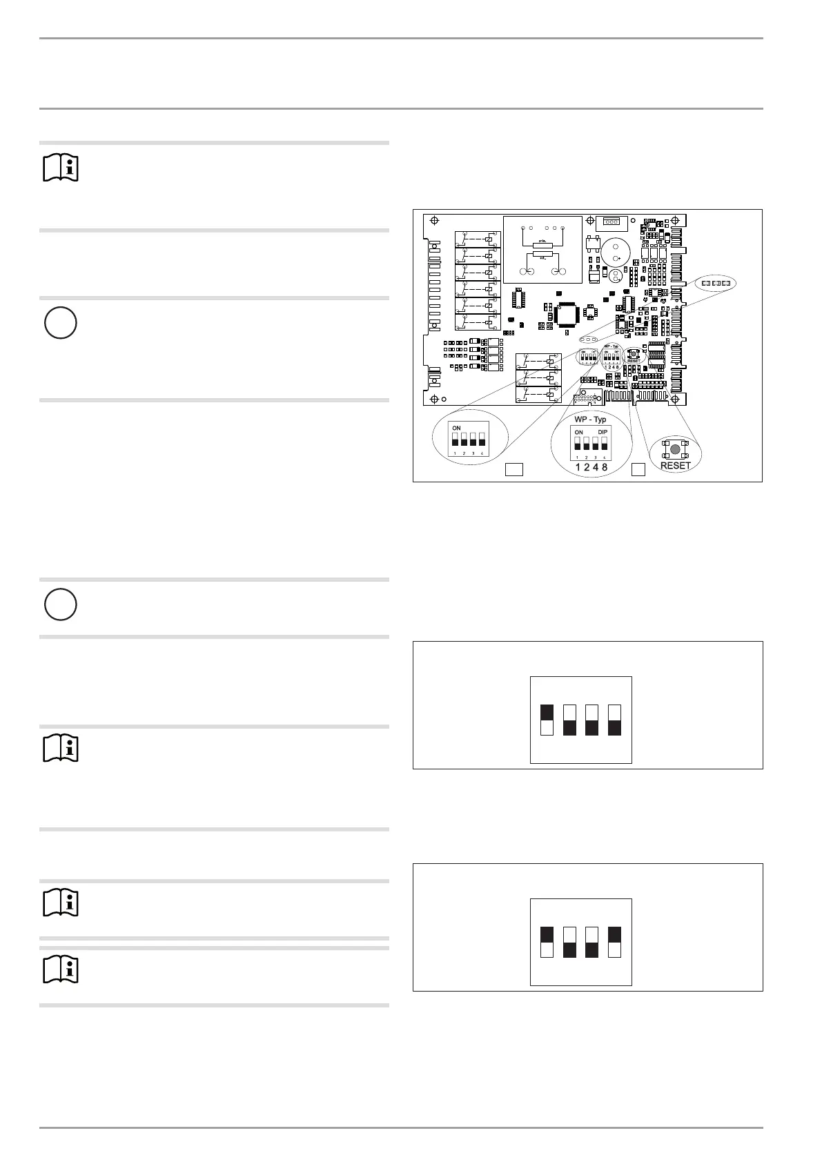
15.1 Elements on the IWS
The IWS (integral heat pump controller II) helps you to trouble-
shoot if the fault cannot be identified using the WPM.
BA
BA
3
4
26�03�01�0921
1 LEDs
2 Reset switch
3 DIP switch (HP type)
4 DIP switch (BA)
15.1.1 Checking the “HP type” DIP switch on the IWS
Check whether the “HP type” DIP switch (3) is set as follows:
With electric booster heater (DHC):
WP - Typ
ON
1 2 3 4
D0000057054
With second heat source:
If the appliance is operated in dual mode with an external
second heat source, set the DIP switch as follows:
WP - Typ
ON
1 2 3 4
D0000057055
In this case, do not connect the power supply for the electric
booster heater (DHC).