26 | WPL basic | WPL S basic www.stiebel-eltron.com
INSTALLATION
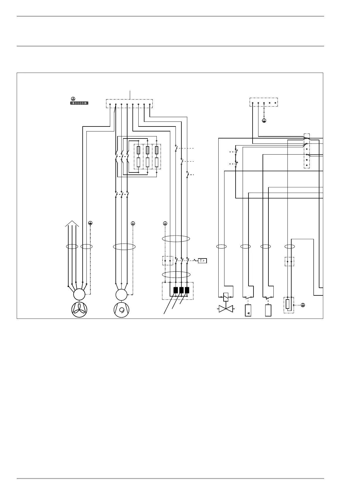
Specication
A2 Integral heat pump controller (IWS)
B1 Heat pump flow temperature sensor - KTY
B2 Heat pump return temperature sensor - KTY
B5 Hot gas temperature sensor - KTY
B6 Intake air temperature sensor - PT1000
B7 Compressor intake temperature sensor - PT1000
B8 Evaporator discharge temperature sensor - PT1000
B9 Frost protection temperature sensor - KTY
B10 Injection temperature sensor - PT1000
E1 Instantaneous water heater (DHC)
E2 Oil sump heater
F2 High pressure switch
F5 High limit safety cut-out DHC
F7 Fan temperature limiter
K1 Resistance start contactor
K2 Compressor start contactor
K5 Instantaneous water heater relay
K6 Instantaneous water heater relay
K7 Instantaneous water heater relay
M1 Compressor motor
M6 Fan motor
M7 Stepper motor el. expansion valve
N2 Differential pressure switch - defrost
P1 High pressure sensor
P3 Low pressure sensor
R1 Starting resistance
R2 Starting resistance
R3 Starting resistance
X1 Terminals
X2 Low voltage terminal strip
X3 Mains terminal
X4 Control terminals
X23 Power supply earth block
X29 12-pin IWS plug - control unit
X30 3-pin IWS plug - BUS
X31 DHC terminal
X33 5-pin IWS plug - el. expansion valve
X34 7-pin IWS plug - sensors
X35 6-pin IWS plug - temperature sensors
X38 3-pin IWS plug - DHC
X39 Pressure sensor terminal
X40 Temperature sensor ground terminal
Y1 Diverter valve - defrost
17.4 Wiring diagram WPL basic standard appliance (3-phase)
X1
Y1
K2
p >
3
2
N2 F2
> p
21
22
22
21
K1
X31
E2
1
2
B5
T
B6
T
B7
T
B8
T
B2
T
X2
M7
M
_
1A 2A
1A 2A
A B
A B
A B
K1
K2
K5
K6
K7
1
2
3
4
1
2
3
4
5
6
7
8
9
10
11
12
1
2
3
H
“+”
1 2 3 4
1
rt sw ge ws
X38
3
2
1
6
5
4
3
2
1
3
2
1
7
6
5
4
3
2
1
5
4
3
2
1
3 2 1
p
P3
3 2 1
p
P1
B9
T
B1
T
N
1
642
M1
M
3~
1 3 5
K2
K1
2 4 6
531
K5
3
3
3
1
1
C
S R
E1
3222
3121
F5
X23
WP
P2=3000W
P3=3200W
DHC
NETZ
12
11
P1=2600W
K6
K7
M6
5
6
M
1~
R2R3
R1
X3
1 2 3 4 5 6 7 8
X23X23
X31
4 3
X23
X4
5
L N PE
1 2 3 4
X23
2.WE
Ext.St.
NETZ
STEUERUNG
L
N
A2/X36
L1 L2 L3 N L1 L2 L3
26�03�01�1624�