18 | WPL basic | WPL S basic www.stiebel-eltron.com
INSTALLATION
Electrical connection
Hang the film with the pre-cut holes onto the hooks on the
appliance.
26�03�01�1455
Remove the backing from the adhesive strips on the frame
and on the plastic film.
Secure the plastic film by pressing it onto the appliance.
Seal the gaps around the hooks with fabric tape.
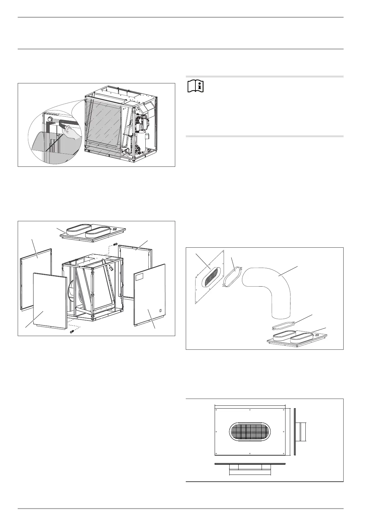
Fitting casing components
2
1
3
1
4
26�03�01�1443
1 Side panel
2 Cover
3 Front panel
4 Back panel
Position the cover on the appliance, and secure it with two
screws.
Hook the side panels and front and back doors onto the
standard appliance. Secure these with a screw each.
Affix the type plate supplied to the front at the top in a clearly
visible location on the r.h. or l.h. side panel of the appliance.
11.2 Routing air hoses
Note
In the case of heat pumps installed indoors, if a blower
door test to EN 13829 is to be carried out, then all aper-
tures which are purposely provided in the building en-
velope must be closed or sealed off before the air hoses
are installed.
For the blower door test, seal off the heat pump’s
supply air and extract air ducts.
You can extend the air hoses by unwinding the coils. There should
be an overlap of approx. 30 cm. The total length of hoses on the
air intake and discharge side must not exceed 8 m.
Never incorporate more than four 90° bends. The radius of the
bends must be at least 600 mm (relative to the centre line of the
hose).
Cut to size using a sharp knife. The Bowden core can be cut
with wire cutters.
Secure the air hose at approx. 1 m intervals. This prevents
the hose from sagging because of its flexibility.
Match the air hose ends to the shape of the oval connectors
on the cover and the hose connection plates. The hose con-
nection plates are available as accessories.
2
3
1
2
4
26�03�01�0930�
1 Hose connection plate
2 Hose clip (oval)
3 Air hose
4 Cover
Hose connection plate dimensions
1173
778
302
687
D0000017278