www.stiebel-eltron.com WPL basic | WPL S basic | 13
INSTALLATION
Mounting
10.4.2 Flow rate with low loss header or buffer cylinder
The flow rate can be adjusted using the temperature differential
of the buffer circuit. The value must not fall below the minimum
flow rate.
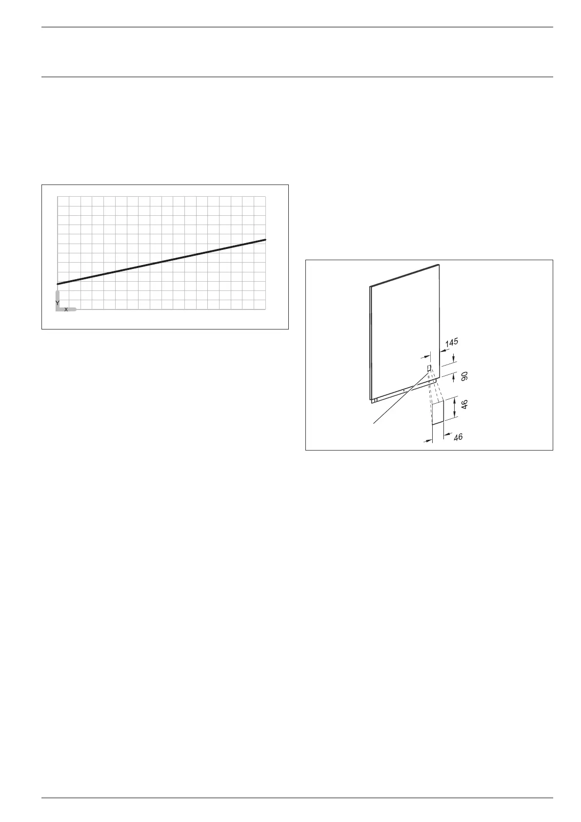
Maximum temperature differential on the heating side with low
loss header or buffer cylinder
-15 -10 -5 0 5 10 15 20 25 30
0
2
4
6
8
10
12
84�03�01�0172
X Outside temperature [°C]
Y Maximum temperature differential [K]
Make the settings at the circulation pump when the tempera-
ture differential between the flow and return temperature
has stabilised.
Compare the resulting temperature differential between the
flow and return at the appliance with the diagram “Maximum
temperature differential on the heating side with low loss
header or buffer cylinder”.
Set the delivery head of the heating circuit pump to a level
that safeguards the heating flow rate required to operate the
heat pump (see chapter “Specification / Data table”).
If the appliance will be used for DHW heating, check the set-
ting of the delivery head in DHW mode.
If necessary, adjust the setting of the delivery head to match
the heating circuit pump.
10.4.3 Using highly energy efficient pumps
If you use a highly energy efficient pump as the heating circuit
pump, you will have to adjust the minimum flow rate using the
temperature differential of the heating system.
Set the heating circuit pump to ∆p-constant.
Set ∆p-constant to the value at which the maximum temper-
ature differential of the heating system is reached.
When connecting the electric emergency/booster heater (DHC),
a flow sensor must be connected to the heat pump manager and
installed close to the heat pump at the heating flow.
10.5 Condensate drain
A condensate drain hose is fitted to the defrost pan to enable the
condensate to drain off. The condensate drain hose is delivered
inside the refrigeration unit.
Ensure the condensate drain hose is not kinked.
Route the hose with a continuous fall.
Use a suitable condensate pump if there is insufficient fall.
Observe the building characteristics.
If using a condensate pump, ensure that it is sized for a
pump rate of at least 6 l/min.
10.5.1 External installation
Route the condensate drain hose downwards through the
knock-out “outlet for supply pipe/cable” and out of the
appliance.
Channel the condensate into a drain or allow it to drain into a
coarse gravel soakaway. Ensure the pipework is free from the
risk of frost.
10.5.2 Internal installation
You can route the condensate drain hose to the left or right
through the knock-out “outlet for condensate drain” (see chapter
“Specification / Dimensions and connections / Internal installa-
tion”) and out of the appliance.
26�03�01�0956
1
1 Knock-out “outlet for condensate drain”
Use pliers to break out the knock-out “outlet for condensate
drain” from the l.h. side panel.
Route the condensate drain hose to the left or right out of the
appliance.
Route the condensate into a drain.
If a bottom drain is to be used, you can drain the condensate
downwards through the “outlet for supply pipe/cable” in the bot-
tom of the appliance.
Route the condensate drain hose diagonally through the
knock-out aperture “outlet for supply pipe/cable”.
Secure the condensate drain hose to ensure it does not slip
out of place.
Route the condensate into the bottom drain.
10.6 Checking the condensate drain
After routing the condensate drain hose, check that the condensate
can drain correctly. Proceed as follows:
Pour water onto the evaporator, which will then flow into
the defrost pan. Please note the maximum condensate drain
capacity of 6 l/min.
Check whether the water is draining off via the condensate
drain hose.