10 | WPL basic | WPL S basic www.stiebel-eltron.com
INSTALLATION
Mounting
9.4 Electrical installation
DANGER Electrocution!
Carry out all electrical connection and installation work
in accordance with national and regional regulations.
DANGER Electrocution!
Only use a permanent connection to the power supply.
The appliance must be able to be separated from the
power supply by an isolator that disconnects all poles
with at least 3mm contact separation. This requirement
can be met by contactors, isolators, fuses etc.
Note
The specified voltage must match the mains voltage. Ob-
serve the type plate.
Route cables with the following cross-sections in accordance with
the respective fuse rating:
Fuse rating Cable cross-section
C 16 A
2.5 mm²
1.5 mm² with only two live cores and routing on a wall or in
an electrical conduit on a wall
C 25 A 6.0 mm² for routing through a wall
4.0 mm² for routing multi-core cables on a wall or in an
electrical conduit on a wall
C 35 A 6.0 mm² for routing multi-core cables on a wall or in an
electrical conduit on a wall
The electrical specifications are given in the “Data table”. The BUS
cable requires a cable J-Y (St) 2x2x0.8mm².
Note
Provide separate fuses/MCBs for the 3 power circuits of
the appliance, the control unit and the electric booster
heater.
9.5 Buffer cylinder
A buffer cylinder is recommended to ensure trouble-free appliance
operation. The buffer cylinder not only provides hydraulic separa-
tion of the volume flow in the heat pump and heating circuit, but
also serves as an energy source for defrosting the evaporator.
10. Mounting
10.1 Handling
Pay attention to the appliance’s centre of mass when trans-
porting the appliance.
The centre of mass is located in the compressor area.
- Lifting slings for transporting the standard appliance can be
hooked in anywhere on the lower frame.
Protect the appliance against heavy impact during transport.
- Only allow the appliance to be tilted during transport for a
short time to one of its longitudinal sides.
The longer the appliance is tilted, the greater the distribution
of refrigerant oil in the system. Wait approx. 30 minutes be-
fore starting the appliance after it has been tilted.
10.2 Positioning
10.2.1 General information
Undo the fixing screws on the appliance frame and keep
them safe. Two or four screws are provided in the frame
to secure the cover. One screw respectively is provided to
secure the side panels (see also chapter “Fitting the casing
components”).
Note
Fit the casing components only after the electrical and
hydraulic connections have been made.
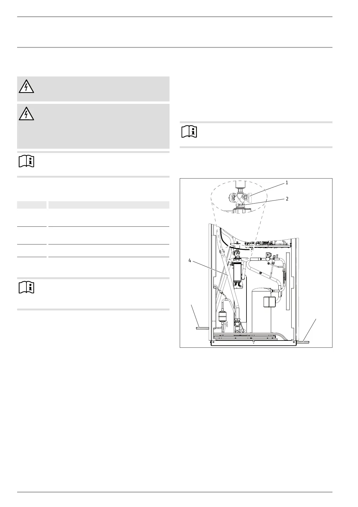
10.2.2 Internal installation
Position the standard appliance on the prepared substrate.
1
2
3
3
26�03�01�1650�
4
1 Connector
2 Union nut
3 Pipe bend, heating circuit return
4 Condensate drain hose
Undo the union nut from the heating flow.
Rotate the connector approx. 145°.
Retighten the union nut.
Fit the pipe bend for the heating circuit return (part of the
“Internal installation accessories”).
Route the condensate hose out of the appliance, either on the
r.h. or the l.h. side.