6 | WPL basic | WPL S basic www.stiebel-eltron.com
INSTALLATION
Safety
INSTALLATION
7. Safety
7.1 General safety instructions
- Only qualified contractors should carry out installation, com-
missioning, maintenance and repair of the appliance.
- We guarantee trouble-free function and operational reliabil-
ity only if the original accessories and spare parts intended
for the appliance are used
7.2 Instructions, standards and regulations
Note
Observe all applicable national and regional regulations
and instructions.
8. Appliance description
For external installation the appliance offers additional frost pro-
tection of the heating water pipes. The integral frost protection
circuit starts the circulation pump in the heat pump circuit auto-
matically at +8 °C condenser temperature, and thereby ensures
circulation in all water-filled sections. The heat pump is started
automatically no later than when the temperature inside the buffer
cylinder drops below +5 °C.
Air hoses guide the intake air from the outside to the appliance and
route the discharge air from the appliance to the outside. These
are highly flexible, thermally insulated and are self-extinguishing
in case of fire in accordance with ASTMD1692-67T.
8.1 Standard delivery
8.1.1 Standard appliance
- Type plate
- Wiring diagram
8.1.2 Required accessories, external installation
The appliance casing components are supplied in a separate pack.
Description
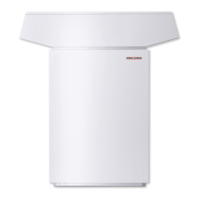
Accessory for outdoor installation WPL .. Basic
Accessory for outdoor installation WPL 13/18/23 A
8.1.3 Required accessories, internal installation
The appliance casing components are supplied in a separate pack.
Description
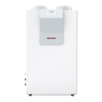
Accessory for indoor installation WPL 13/18/23 I
WPIC
WPIC B
8.2 Accessories
8.2.1 Required accessories, internal and external installation
Description
Heat pump manager WPMS 3 or WPMW 3
Remote control for heating systems
Contact sensor
Immersion sensor
8.2.2 Additional required accessories for internal installation
Description
Thermally insulated air hose, 3m or 4m long
Hose connection plate
Wall outlet AWG 560
8.2.3 Further accessories
Description
Buffer cylinder
Pressure hose G 1¼ x 1 m (DN 32)
Pressure hose G 1¼ x 2 m (DN 32)
Pressure hose G 1¼ x 5 m (DN 32)
Pressure hose G 1¼ x 1 m (DN 32), can be trimmed
Hose fittings for pressure hose G 1¼ (DN 32)
Condensate pump
9. Preparations
9.1 Acoustic emissions
On the air intake and air discharge sides, the appliance is louder
than on the enclosed sides. Observe the following information
when selecting the installation location.
Note
For details regarding the sound power level, see chapter
"Specification / Data table".
9.1.1 Sound emissions for external installation
- Lawn areas and shrubs contribute to the reduction of noise.
- Noise propagation can also be reduced through dense pali-
sades or similar.
Ensure that the air intake direction is in line with the main
wind direction. Air should not be drawn in against the wind.
Never direct the air intake or discharge towards noise-sensi-
tive rooms of the house, e.g. bedrooms.
Avoid installation on large, echoing floor areas, e.g. tiled
floors.
Avoid installation between reflective building walls. Reflec-
tive building walls can increase the sound level.
Note
Provide a recess (space) in the substrate to enable water
and electrical pipes/cables to be connected from below.
Also observe the chapter “Installation/Siting”.

 Loading...


