16 | WPL basic | WPL S basic www.stiebel-eltron.com
INSTALLATION
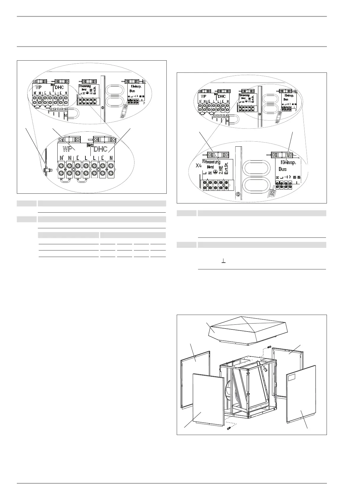
Electrical connection
PE
1
2
26�03�01�1652�
1 Power supply (heat pump, compressor)
L, N, PE
2 Elect. booster heater (DHC)
L, L´, N, PE
Connected load Terminal assignment
3.0 kW L N PE
3.2 kW L´ N PE
6.2 kW L L´ N PE
Cover and seal the mains terminal (X3) when all electric ca-
bles have been connected.
Terminals X4, X2, control and LV
X2
X4
1
2
26�03�01�1651�
1 Control terminals
Power supply: L, N, PE
Control inputs:
2. Heat source
Ext. ST Stand alone operation
2 LV terminal
BUS high H
BUS low L
BUS ground
BUS “+” (not connected)
11.1 Fitting casing components
11.1.1 Fitting the casing components for the standard external
installation
2
1
3
1
4
26�03�01�0929
1 Side panel
2 Cover
3 Front panel
4 Back panel