EN
SYMBOLS 3
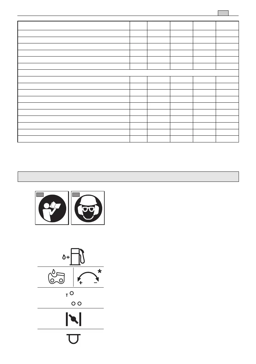
1) Read the instruction manual before using the
machine.
2) If you are using the machine every day in nor-
mal conditions, you can be exposed to a noise
level of 85 dB (A) or higher. Wear a protective
helmet, ear plugs and goggles.
11) Fuel tank
12) Chain oil tank and oil flow adjuster
(only for mod. 46/52)
13) Carburettor adjustments
T = idle speed adjuster
(L) = low speed mixture adjuster
(H) = high speed mixture adjuster
14) Choke
15) Primer
EXPLANATORY SYMBOLS ON THE MACHINE (if present)
2. SYMBOLS
Maximum noise and vibration levels
[1]
Model
36 43 46 52
Operator ear noise pressure level (ISO 22868) dB(A) 98,9 98,9 102,3 101,6
– Measurement uncertainty (2006/42/EC - EN 27574) dB(A) 2,5 2,5 2,5 2,5
Measured acoustic output level
(ISO 22868)
dB(A) 108,1 108,1 113 113,4
– Measurement uncertainty (2006/42/EC - EN 27574) dB(A) 2,5 2,5 2,5 2,5
Vibration level (
ISO 22867)
m/sec
2
7,5 - 6,2 7,5 - 6,2 4,9 - 3,6 5,7 - 4,9
– Measurement uncertainty (2006/42/EC - EN 12096) m/sec
2
0,5 0,5 0,5 0,5
TECHNICAL SPECIFICATIONS
Engine (2-stroke single cylinder) – displacement
cm
3
36,3 40,2 45 52
Fuel (petrol/oil) % 50:1 = 2 % 50:1 = 2 % 50:1 = 2 % 50:1 = 2 %
Power kW 1,5 2,0 2,2 2,4
Idle RPM
1
/min
2800
±
150 2800
±
150 2800
±
150 2800
±
150
Maximum admissible rpm without load with chain installed
1
/min
11300 12000 12500 12500
Fuel tank capacity
cm
3
370 370 500 500
Maximum power specific consumption g/kWh 490 410 510 500
Oil tank capacity
cm
3
190 190 300 300
Chain pinion teeth 6 7 7 7
Weight (with empty tank) kg 4,2 4,1 4,7 4,7
[1] WARNING! The vibration value may vary according to the usage of the machine and its fitted equipment, and be higher than
the one indicated. Safety measures must be established to protect the user and must be based on the load estimate generated
by the vibrations in real usage conditions. In this regard, all the operational cycle phases must be taken into consideration, such
as switching off or idle running.
 Loading...