Remove the flywheel - see 5.4.
Remove the piston - see 4.5.1.
•
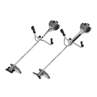
Take out the screws.
•
Place extension (1) 4116 894
1000 on crankshaft stub at clutch
side of crankcase.
•
Back off spindle (left-hand
thread) of ZS installing tool (1)
5910 890 2220 a little.
•
Hold ZS installing tool against
clutch side of crankcase so that
the notch marked "16" is at the
bottom.
•
Insert M6x20 screws (2) in holes
marked "17" and tighten them
down against the drilled plate.
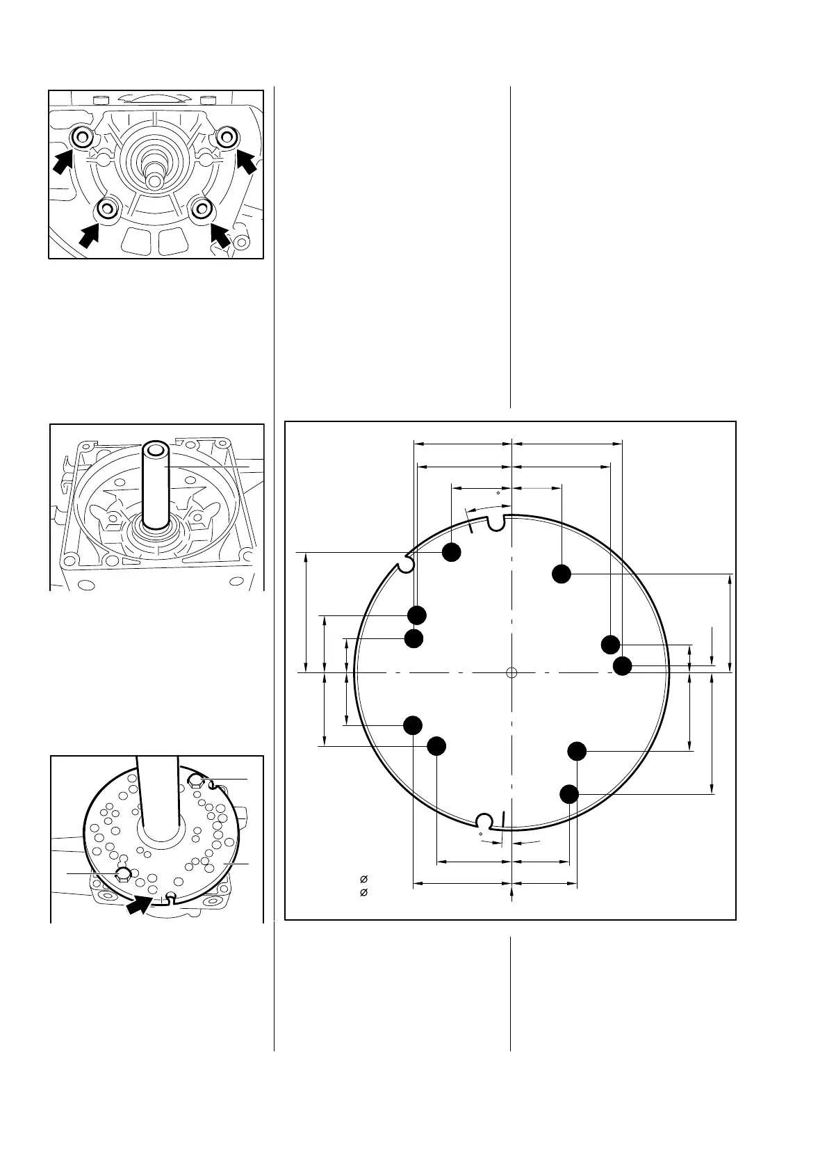
Note: ZS installing tools without
holes "16", "17" and "18" and
notches "16" and "17" can be
modified as shown in the
illustration.
Holes "16" and "18" are needed at
the starter side of the crankcase.
The illustration shows the under-
side of the drilled plate.
250RA056
VA
250RA062
1
VA
17
250RA063
2
17
16
2
1
VA
41.25
33.85
9.7
26.85
2.25
250RA219
17.3
33.3
38.0
33.6
20.6
32.25
22.5
41.6
25.5
33.7
20.1
17.65
12.6
24.75
17
19.9
18
16
18
16
16
17
18
16
18
17
16
1
2.5
15.5
16 + 18 = 5,5
17 = 6,5
VA
)6)5
 Loading...