► Plug the mains plug (6) into an easily accessi‐
ble socket (7).
The charger (3) will run a self-test. The
LED (4) will glow green for about 1 second
and red for about 1 second.
► Routing the connecting cord (5).
► Insert the battery (2) in the guides in the
charger (3) and press it home as far as stop.
The LED (4) glows green. The LEDs (1) glow
green and the battery (2) is being charged.
► When the LED (4) and the LEDs (1) on the
battery no longer light up: The battery (2) is
fully charged and can be removed from the
charger (3).
► If the charger (3) is no longer required. Dis‐
connect the mains plug (6) from the wall outlet
(7).
6.3 State of Charge
1
0000-GXX-0629-A0
20-40%
40-60%
60-80%
80-100%
0-20%
► Press the button (1).
The LEDs (5) glow green for about 5 seconds
and indicate the state of charge.
► If the LED on the right flashes green: Charge
the battery.
6.4 LEDs on Battery
The LEDs can show the state of charge or mal‐
functions. The LEDs can glow or flash green or
red.
The state of charge is indicated when the LEDs
glow or flash green.
► If the LEDs glow or flash red: Troubleshooting,
19.1.
Malfunction in trimmer or battery.
6.5 LED on Charger
The LED indicates the operating status of the
charger.
If the LED glows green, the battery is being
charged.
► If the LED flashes red: Rectify the malfunction.
Malfunction in charger.
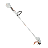
7 Assembling the Trimmer
7.1 Attaching the deflector
► Switch off the brushcutter and remove the bat‐
tery.
The line limiting blade (1) has already been
installed in the guard (2) and must not be
removed.
► Push the deflector (2) into the guides on the
gear housing up to the limit stop.
► Insert the screw (3) and tighten it securely.
7.2 Removing the Deflector
► Switch off the brushcutter and remove the bat‐
tery.
► Unscrew the screw (2).
► Pull off the deflector (1).
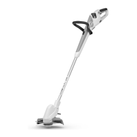
7.3 Attaching the loop handle
► Switch off the brushcutter and remove the bat‐
tery.
English 7 Assembling the Trimmer
14 0458-027-0101-A
 Loading...