ASTOPAD
®
Instructions for Use
25
7 Operating states
With a few exceptions, the operating states when only one applied part is con-
nected to the ASTOPAD control unit at output A and is being operated are de-
scribed below.
The description of the operating states applies to the connection and operation of
a second applied part to output B of the ASTOPAD control unit.
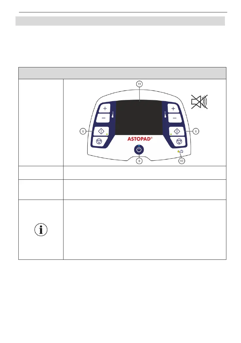
After connecting the mains plug to the mains socket, the con-
trol unit is in Standby mode.
The Standby LED (9) lights up.
The display (11) shows the symbol for battery status (only
for equipment with built-in battery).
Press the Standby button (9) to switch the equipment from
any mode to Standby mode.
In Standby mode only the electronics and the applied parts
are disconnected from the power supply. The control unit
remains connected to the mains.
For equipment with a built-in battery, the battery is charged
in Standby mode.
After a power failure, the equipment automatically switches
to Standby mode.