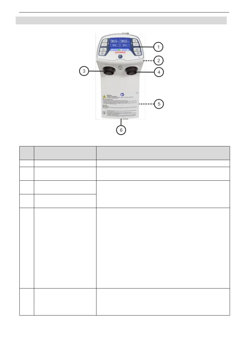
EasyManua.ls Logo

STIHLER ELECTRONIC ASTOPAD DUO310 - Components of the ASTOPAD

STIHLER ELECTRONIC ASTOPAD DUO310
66 pages
Print Icon
To Next Page IconTo Next Page
To Previous Page IconTo Previous Page
Loading...
ASTOPAD
®
Instructions for Use
6 Product description
22
6.3 Components of the ASTOPAD
Control unit
Fig. 1 Control unit
No
.
Designation
Description
1
Control panel
Operating buttons and temperature displays.
2
Fastening device
For secure attachment of the ASTOPAD control
unit.
3
Output A
(connecting socket)
Plug-in connection to connect the applied part.
4
Output B
(connecting socket)
5
Connection for poten-
tial equalisation
The additional potential equalisation has the task
of equalising potentials of various metal parts
which can be touched at the same time or of re-
ducing potential differences that can arise in the
application between the body, electromedical
equipment and foreign conductive parts.
The connection is made via green-yellow insu-
lated cables (min. 4 mm²) on standardised con-
nection bolts and connection sockets.
When connecting/combining ME devices to form
an ME system, the requirements of IEC/EN
60601-1 must be observed.
6
Device plug for de-
tachable mains con-
nection cable with
mains plug
The mains connection cable supplies the control
unit with mains voltage via a plug. The device is
disconnected from the power supply by pulling
out the mains plug.

Table of Contents