ASTOPAD
®
Instructions for Use
24
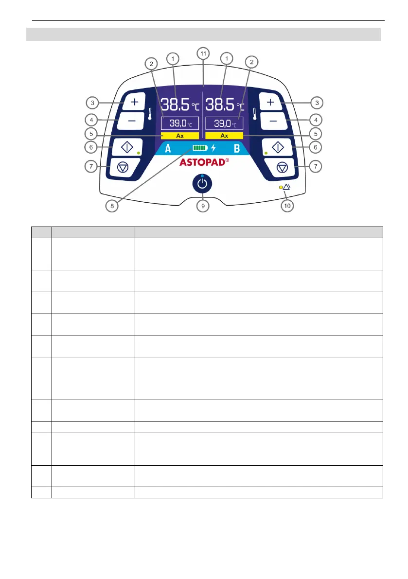
6.4 Control panel
Fig. 3 Control panel
Actual
temperature
A or B
Displays the actual temperature of the applied part.
Displays the selected set temperature of the applied part.
Press this button to increase the set temperature in
increments of 0.5°C.
Press this button to decrease the set temperature in
increments of 0.5°C.
Displays the corresponding alarm code in an alarm situa-
tion.
Start button
Start LED (green)
A or B
Press this button to start the heating process.
or
Press this button to confirm a change made to the set tem-
perature.
Ends the heating process and switches off the respective
output.
Shows the current battery charge level or battery status.
Standby button
Standby LED
(blue)
The Standby button switches between Standby mode and
On mode.
LED flashes or lights up and the acoustic alarm signal
sounds when there is an alarm situation.
Informs the user of temperatures and fault conditions.