EN
English–15
5.1-Programmingwarnings
•Ingeneral
-Strictlyobservethetimelimitsspeciedintheprocedures.
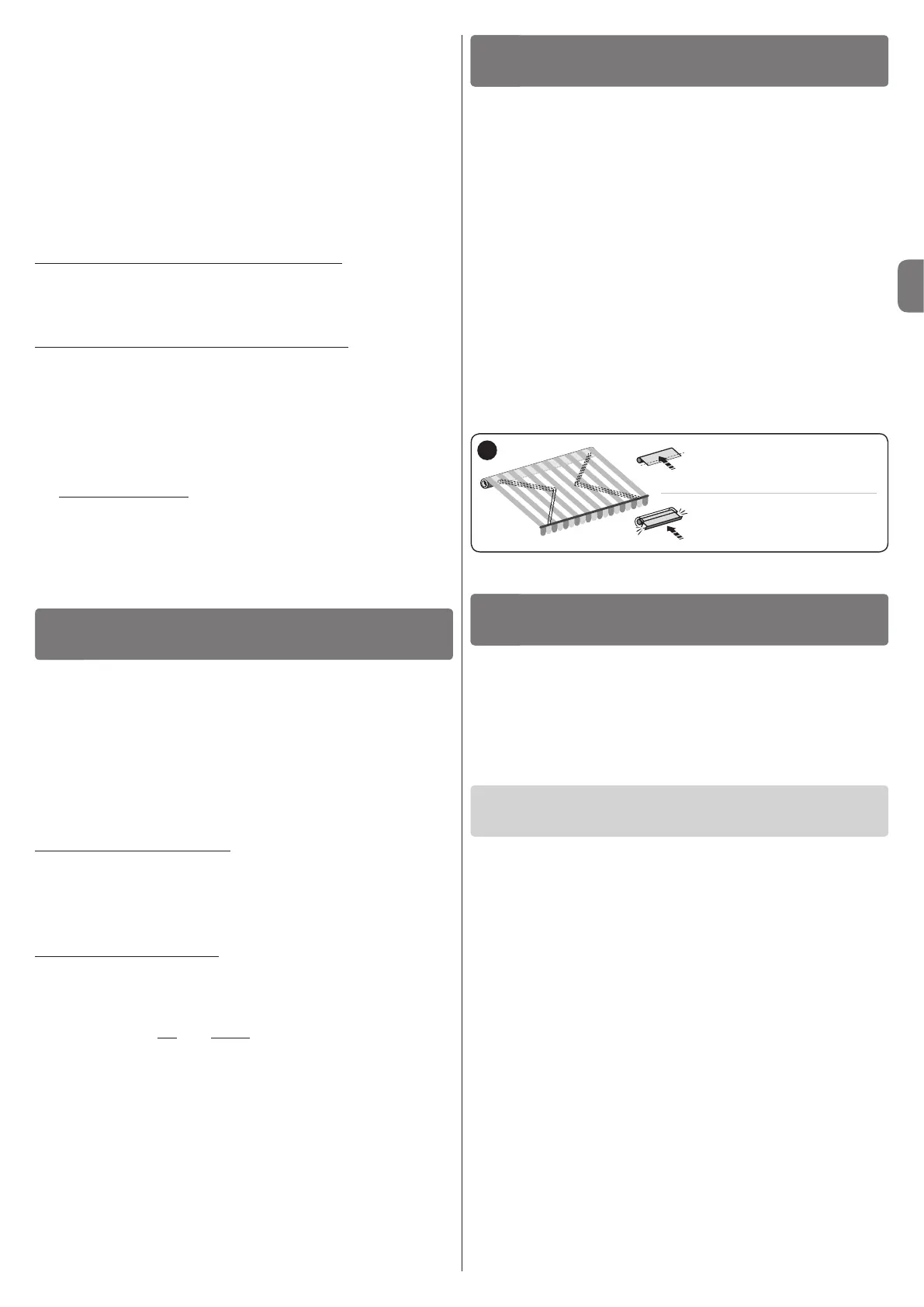
-Positions0,1oftheawning,speciedinthetext,correspondtothoseillustratedin
fig. 14.
-Duringinstallationandadjustment,whilenalelectricalconnectionsarestilltobe
made,thesystemcanbecontrolledwiththespecic“MA2001/MA2002”unit
(fig.15).
5.2-Limitswitchprogramming
Limitswitches“0”and“1”(fig. 14)correspondtothepositionsoftheawningatthe
endoftheUpmovements(“0”)andtheendoftheDownmovements(“1”).
Toselecttheproceduremostsuitedtothesystemfeatures,refertofig. 17.
5.3-Noteon“RDC”function
TheRDCfunctionpreventsthecanvasfromremainingexcessivelytensionedatthe
endoftheclosingmanoeuvre.Thefunctionautomaticallyreducesthemotortraction
torqueduringthenalphaseoftheclosingmanoeuvre(tosettherequiredtorque
value,refertoparagraph5.6).
Thisfunctionisenabledbydefault,butwillnotworkifthelimitswitchesarepro-
grammedusingthemanualprocedure(paragraph5.4).
Caution!
-Incorrectconnectionscancausefaultsorhazardoussituations.
-Strictlyobservetheconnectionsspeciedinthismanual.
-Adisconnectdevicemustbeinstalledontheproductpowersupplyline,withagap
betweencontactstoensurecompletedisconnectioninovervoltagecategoryIII,in
compliancewithinstallationregulations(thedisconnectdeviceisnotsuppliedwith
theproduct).
Tomaketheelectricalconnections,refertothewiringdiagraminfig. 11.Thedia-
gramshowstheconnectionbetweenthetwomotors,connectionofacontrolpush-
buttonpanel,connectiontothemainsandconnectiontoaswitchfordisconnection
fromthemains.Thefollowingtableshowsthepurposeofeachwire.
“MASTER”motorcable–6wires:
1 - Yellow-green:=System“earth”(equipotentialbondingconnection).
2 - Blue:=System“Common”(usuallyconnectedtoNeutral).
3 - Brown:=systemelectricalascent(ordescent)phase.
4 - Black:=systemelectricaldescent(orascent)phase.
5 - Violet:=“slave”motorelectricalascent(ordescent)phase.
6 - Red:=“slave”motorelectricaldescent(orascent)phase.
“SLAVE”motorcable–4wires:
7 - Violet:=“slave”motorelectricalascent(ordescent)phase.
8 - Red:=“slave”motorelectricaldescent(orascent)phase.
9 - Blue:=“Common”(usuallyconnectedtoNeutral).
10 - Yellow-green:=“Earth”(equipotentialbondingconnection).
•AssociatingtheUpandDownmovementswiththerespec-
tivepushbuttons
Aftermakingtheconnections,runanumberofmanoeuvres(*)toensurethatthe
ascentanddescentmovementsareassociatedcorrectlywiththerespectivecontrol
buttons.Ifthisisnotso,inverttheconnectionoftheBrownandBlackwires.
ELECTRICALCONNECTIONS
4
PROGRAMMING
5
Whattodoif…
(troubleshooting guide)
6.1-Maximumcontinuousworkcycle
Ingeneralthetubularmotors,whileguaranteeingamaximumcontinuoususeof
4minutes,aredesignedforresidentialapplicationsandthereforefordiscontinu-
oususe.Thereforeintheeventofoverheating(forexampleduetocontinuousand
prolongedactivation)athermalcut-outtripsautomaticallytoshutoffpowersupply.
Powerisonlyrestoredwhenthetemperaturereturnstowithinthenormalrange.
WARNINGSFORDAILYUSEOF
THEAUTOMATION
6
q When an electrical phase is powered up, the system does not move:
Providedthatathermalcut-outhasnottripped,inwhichcaseitissufcientto
waitforthesystemtocooldown,performthefollowingchecks.
•Ensurethatthemainsvoltagecorrespondstothedatastatedinthetechnical
specicationsofthismanual,measuringthevoltagebetweenthe“common”wire
andthatofthepoweredelectricalphase.
•Checktheconnectionbetweenthetwomotorsandthemains.
•Lastly,trypoweringuptheoppositetheelectricalphase.
q When a command is sent, the system seems to start (a noise can be heard)
but fails:
•Checktheconnectionbetweenthetwomotorsandthemains.
•Athermalcut-outononeofthetwomotorsmayhavetripped;waitfortherela-
tivemotortocool.
•Ensurethatthedirectionofrotationofthetwomotorsiscoordinatedtoenable
theawningtomoveupanddown.
q The system still runs in emergency conditions, i.e. in hold-to-run condi-
tions:
•Checkwhetherthemotorshavebeensubjecttoanelectricshockorsubstan-
tialmechanicalstress.
•Checkthemechanicalconditionofallmotorparts.
•Runthedeletionprocedure(paragraph5.7)andprogramthelimitpositions
again.
Manual procedure
paragraph5.4
Semi-automatic procedure
paragraph5.5
17
3.3-Otherinstallationwork
3.3.1- Changingthedirectionofthecableoutlet
(onMOVENOTandemZversiononly)
Tochangethedirectionofthecableoutlet,refertofig. 6:
01. Pulltheprotectioncoverinthedirectionofthearrowtoremove.
02. Bendthecableintherequireddirection.
03. Re-ttheprotectioncoverbypressingitrmlyintoitsseat.
3.3.2- Replacingadamagedpowercable
(onMOVENOTandemYandMOVENOTandemZversions
only)
Ifthepowercable(orconnector)isdamaged,itmustbereplacedwithanidenticalversion
availablefromSTOBAGTechnicalAssistance.
Replacing the cable on the MOVENO Tandem Y motor (fig. 9):
A.
Turntheringnuttoalignthechamferededgewithoneofthecouplingteeth,then
release.
B. Repeatthesameoperationfortheothertooth.
C. Bendthecableinwardsandremovetheprotectionbyturningitgentlyoutwards.
D. Pulltheconnectorouttoremove.
Replacing the cable on the MOVENO Tandem Z motor (fig. 10):
A.
Pulltheprotectionoutwardstoremove.
B. Pulltheconnectorouttoremove.
3.3.3-Installingthewall-mountedpushbuttonpanel
Installacontrolpushbuttonpanelonthewall,takingcaretoobservethefollowing:
– EachMOVENOTandemsystemcanbeconnectedandcontrolledviaasingle
pushbuttonpanel(fig. 12).Toconnectit,refertofig. 11.Inthecaseofmultiple
systems,theycannotallbecontrolledviathesamepushbuttonpanel(fig. 13).
– Selecta2-buttonpanel(UpandDown).
– Itisadvisabletousea“hold-to-run”pushbuttoncontrolpanel,i.e.itisnecessary
topressandholdthebuttonforthedesireddurationofthemanoeuvre.
– Positionthepushbuttonpanelinsightoftheawningbutfarfrommovingparts.
– Positionthepushbuttonpaneltothesideoftheawning,wherethe“master”tubu-
larmotorpowercableandthemainspowercablearelocated.
– Positionthepushbuttonpanelataheightofatleast1.5mfromtheground.
www.stobag.com