7 | Installation STOBER
34
03/2020 | ID 442793.03
7.3 Minimum clearances
Note the minimum clearances for installation below.
Drive controller
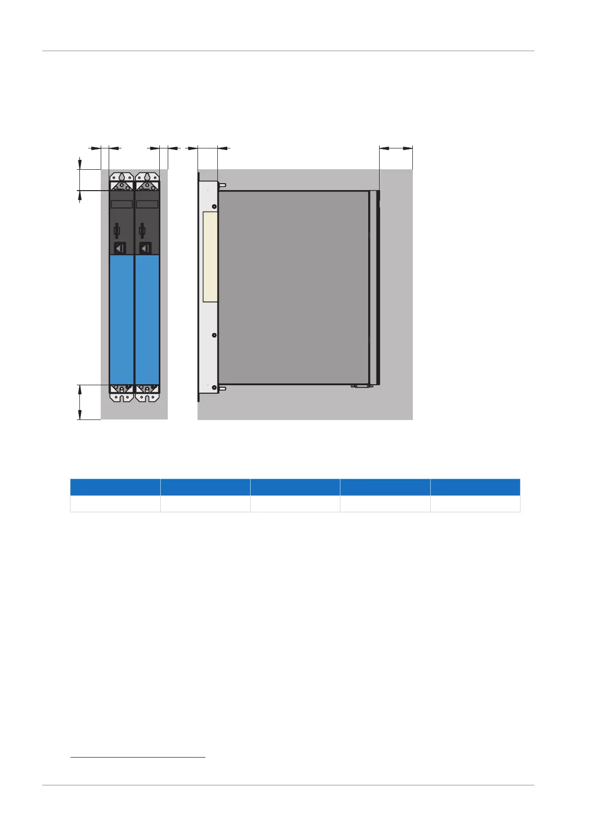
Fig.7: Minimum clearances
The specified dimensions relate to the outer edges of the drive controller.
Minimum clearance A (above) B (below) C (on the side) D (in front)
All sizes 100 200 5 50
3
Tab. 38: Minimum clearances [mm]
Chokes and filters
Avoid installation below drive controllers or supply modules. For installation in a control cabinet, a distance of
approximately 100mm to other neighboring components is recommended. This distance ensures proper heat dissipation
for chokes and filters.
Braking resistors
Avoid installation below drive controllers or supply modules. In order for heated air to flow out unimpeded, a minimum
clearance of approximately 200mm must be maintained in relation to neighboring components or walls and approximately
300mm must be maintained to components above or ceilings.
3
Minimum clearance to be taken into account for permanent connection of the X9 service interface