11 | Appendix STOBER
90
03/2020 | ID 442793.03
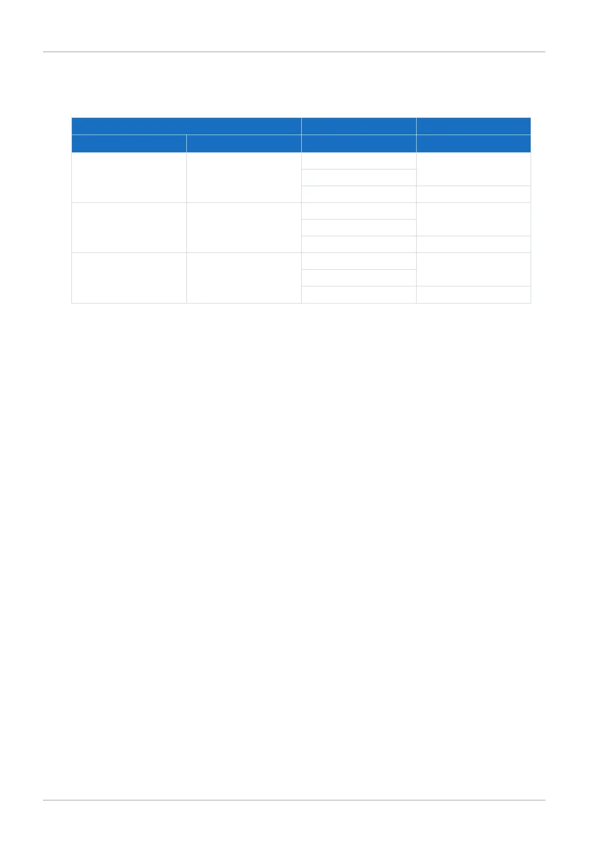
11.3 Order overview of the hardware components
Note that the drive controller is delivered without terminals. Suitable terminal sets are available separately for each size.
Drive controller Safety technology Terminal set
Type ID No. ID No. ID No.
SC6A062 56690 56660
a)
138652
56662
b)
56661
c)
138680
SC6A162 56691 56660
a)
138653
56662
b)
56661
c)
138681
SC6A261 56692 56660
a)
138654
56662
b)
56661
c)
138682
Tab. 97: Overview of hardware components with ID No.
a) SZ6 option (without safety technology)
b) SY6 safety module (STO and SS1 using FSoE)
c) SR6 safety module (STO using terminals)