8 | Connection STOBER
60
03/2020 | ID 442793.03
8.4.11 X12: Safety technology (option SR6)
The SR6 option adds the STO safety function to the SC6 drive controller via terminal X12.
For double-axis controllers, the STO safety function has a two-channel structure that acts upon both axes.
Information
If you would like to use the STO safety function via terminals, be sure to read the manual for the SR6 safety module.
Technical data
Observe the technical data of the safety options for X12; see the chapter Safety technology [}30].
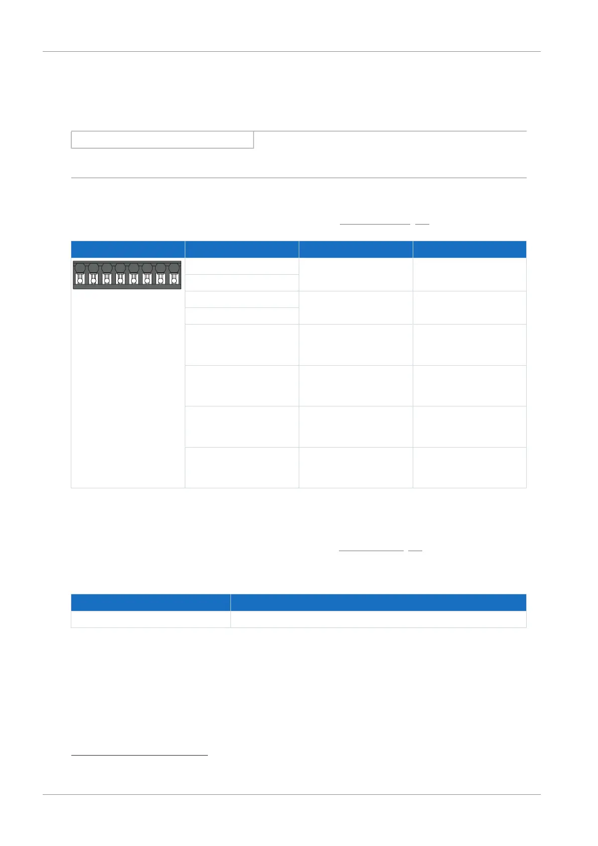
Terminal Pin Designation Function
1|2|3|4|5|6|7|8
1 STO
a
Input of safety channel 1
2
3 STO
b
Input of safety channel 2
4
5 GND Reference potential for STO
a
and STO
b
, internally bridged
with terminal 7
6 STO
status
Acknowledgment signal of
safety channels 1 and 2 for
diagnostic purposes
7 GND Reference potential for STO
a
and STO
b
, internally bridged
with terminal 5
8 U
1status
STO supply
status
;
recommended fuse
protection: max. 3.15AT
7
Tab. 65: X12 connection description
Connecting wiring
For connecting wiring, observe the terminal specifications in the chapter BCF 3,81 180 SN [}85].
Cable requirements
Feature All sizes
Max. cable length 30m
Tab. 66: Cable length [m]
7
For UL-compliance, use of a 3.15A fuse (time delay) is required. The fuse must be certified for DC voltage in accordance
with UL 248.