STOBER 7 | Installation
03/2020 | ID 442793.03
35
7.4 Drilling diagrams and bore dimensions
Drilling diagrams and bore dimensions can be found in the following chapters.
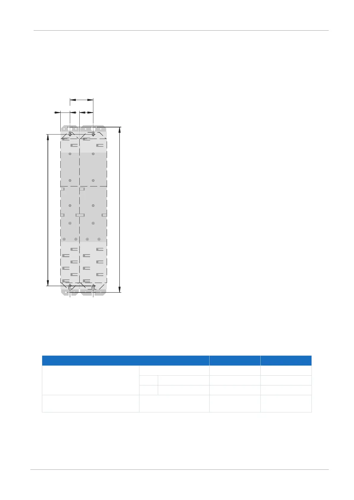
7.4.1 Drive controllers
Fig.8: SC6 and DL6B drilling diagram
The bore dimensions depend on the selected design.
The following specifications apply to installation without a rear section module:
SC6 dimension Size0 Size 1, size2
Horizontal fastening holes
∅4.2 (M5)
A 45 65
B Size0 46±1 56±1
B Size1, size 2 56±1 66±1
Vertical fastening holes
∅4.2 (M5)
C 360+2 360+2
Tab. 39: Drilling dimensions for SC6 drive controller [mm]