8 | Connection STOBER
48
03/2020 | ID 442793.03
8.3.3.2 Connection of the grounding conductor
You connect the grounding conductor to the drive controller over terminal X10.
Additional requirements for protective equipotential bonding apply in the event of ground leakage currents > 10mA.
At least one of the following conditions must be fulfilled:
§ The grounding conductor must have a minimum cross-section of 10mm² Cu over its overall length
§ If the grounding conductor has a cross-section of less than 10mm², a 2nd grounding conductor must be provided with
a cross-section of at least the same size up to the point at which the grounding conductor exhibits the minimum cross-
section of 10mm²
A grounding bolt is mounted to the devices for connecting the 2nd grounding conductor.
You will need an open-ended wrench or external hex key with a width across flats of 10mm.
Note the tightening torque of 4.0Nm, 35Lb.inch.
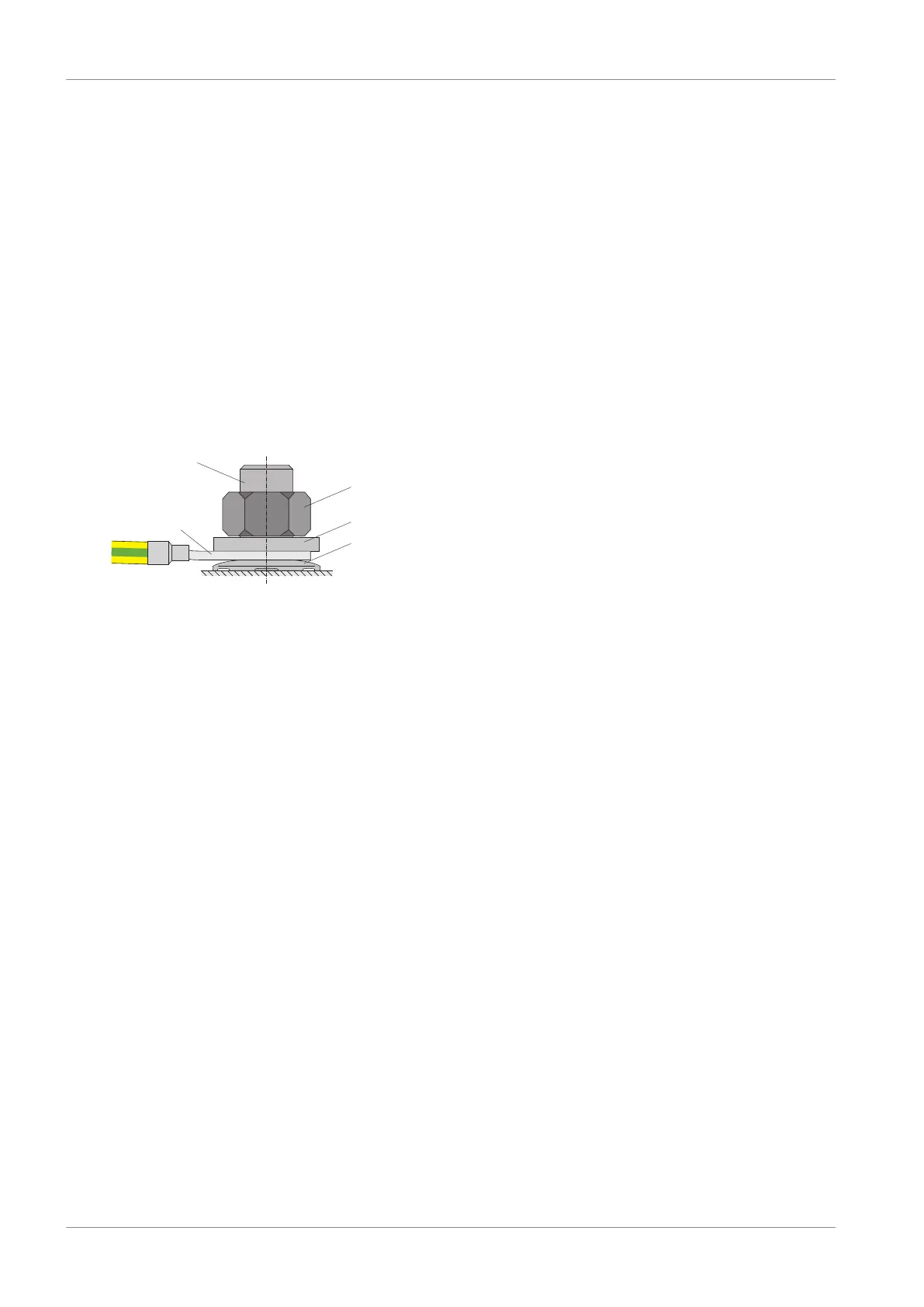
Observe the order for assembly:
Fig.10: Connection of the grounding conductor
1 M6 ground bolt
2 Contact disk
3 Cable lug
4 Washer
5 Nut
The contact disk, washer and nut are supplied with the drive controller.