STOBER 8 | Connection
03/2020 | ID 442793.03
65
Evaluable encoders
The technical data of the evaluable encoders at X103 can be found in the manual for the SC6 drive controller.
Information
Note that a master encoder must be connected to X101 during synchronous operation.
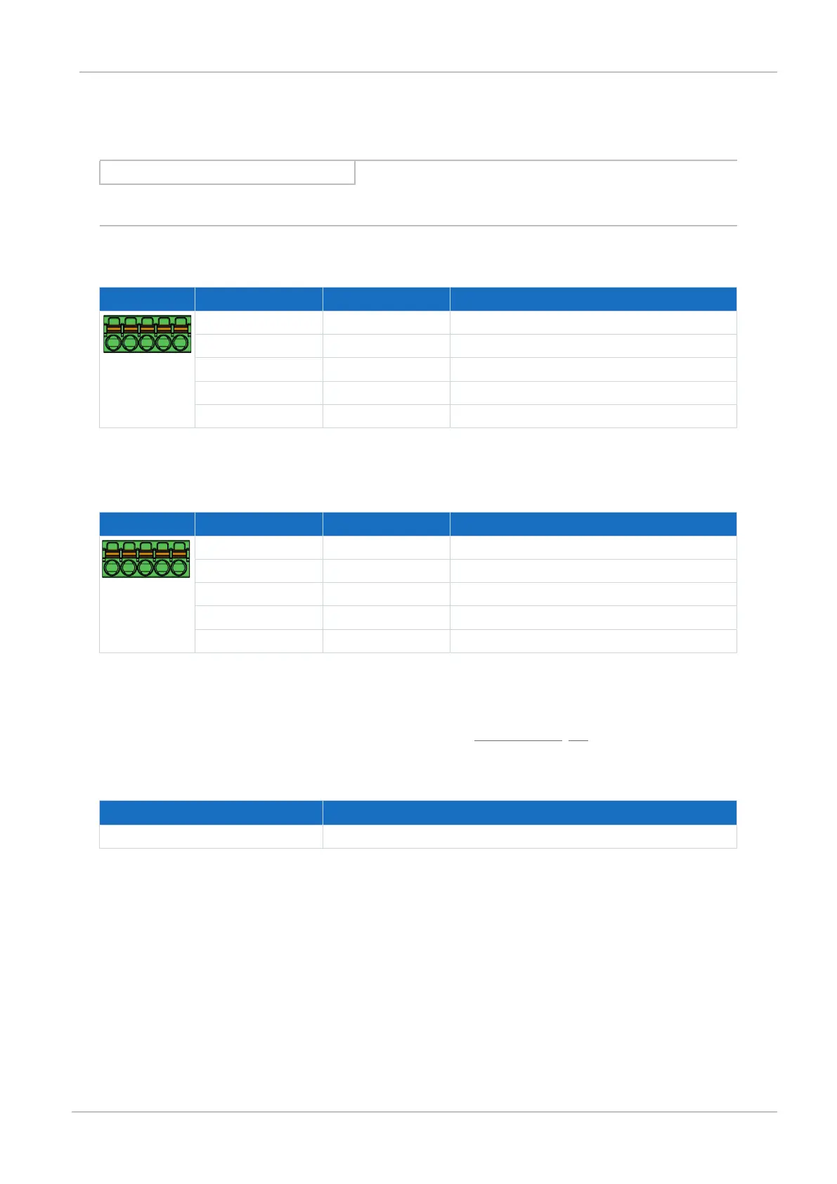
Single-ended HTL incremental encoders
Terminal Pin Designation Function
5|4|3|2|1
1 DI6 ─
2 DI7 N channel
3 DI8 A channel
4 DI9 B channel
5 DGND Reference ground; not bridged with X101, pin 5
Tab. 79: X103 connection description for single-ended HTL incremental signals, axis B
Single-ended HTL pulse train
Terminal Pin Designation Function
5|4|3|2|1
1 DI6 ─
2 DI7 ─
3 DI8 Frequency
4 DI9 Direction
5 DGND Reference ground; not bridged with X101, pin 5
Tab. 80: X103 connection description for single-ended HTL pulse/direction signals, axis B
Connecting wiring
For connecting wiring, observe the terminal specifications in the chapter FMC 1,5 -ST-3,5 [}85].
Cable requirements
Feature All sizes
Max. cable length 30m
Tab. 81: Cable length [m]